Camera Projections In Nuke: Explained
How camera projections work and how you can use them in practice when compositing shots…

How camera projections work and how you can use them in practice when compositing shots…
Camera projection is a very powerful “2.5D” (somewhere in between 2D and 3D) compositing technique, and can for example be used for:
- Re-photographing a shot from a different angle or with a different camera move.
- Tracking a patch to a shot (for example to do clean up work).
- Re-using CG renders or matte paintings from other shots.
- Placing 2D elements (smoke, fire, rain, etc.) into a 3D scene.
- Adding movement and parallax to a still image, such as a matte painting.
- Changing or touching up textures and details on objects in CG renders.
- Stabilising a shot.
However, camera projections can be a little bit confusing if you don’t understand how they work. I’ve seen a lot of compositors making mistakes when setting up projections in their scripts. And many might not know how to make projections stick to animated geometry, for example.
So this guide is meant to explain how it all works and how you can build projection setups that work properly, to do all of the things above and more.
We’ll even do everything using both the classic 3D system and the new 3D system in Nuke, and so those of you familiar with one but not the other can easily compare and contrast.
First, let’s take a look at what a projection is:
Camera Vs. Projector
A camera captures the real world, or a CG environment, through a lens and onto a flat sensor (or film) – turning the three-dimensional scene into a two-dimensional image.
In that process we lose a lot of information about the three-dimensionality of the scene. The camera ‘compresses’ the 3D scene into a flat plane, baking the information that was captured from a single viewpoint into the 2D image.
We can no longer take a peek around a corner (or see a side of an object that’s not facing the camera) in a single two-dimensional image, for example. We’re essentially locked into seeing the viewpoint of the camera which captured the scene, in a flat picture.
A projector works the other way around to a camera: It projects a 2D image through a lens and into a 3D scene. And, importantly, the projection is still limited by the baked viewpoint in the 2D image that’s being projected.
You’re still projecting one viewpoint into a 3D scene, and that projection will be less and less useful the more you move away from the original viewpoint to view the projection.
Let’s take a look at a quick example where we render a 3D scene to a 2D image, and then project that same rendered 2D image back into the same scene (i.e. onto the same geometry) using the same render camera as the projector.
For this example, the 3D scene simply consists of a fully textured vase and a camera:
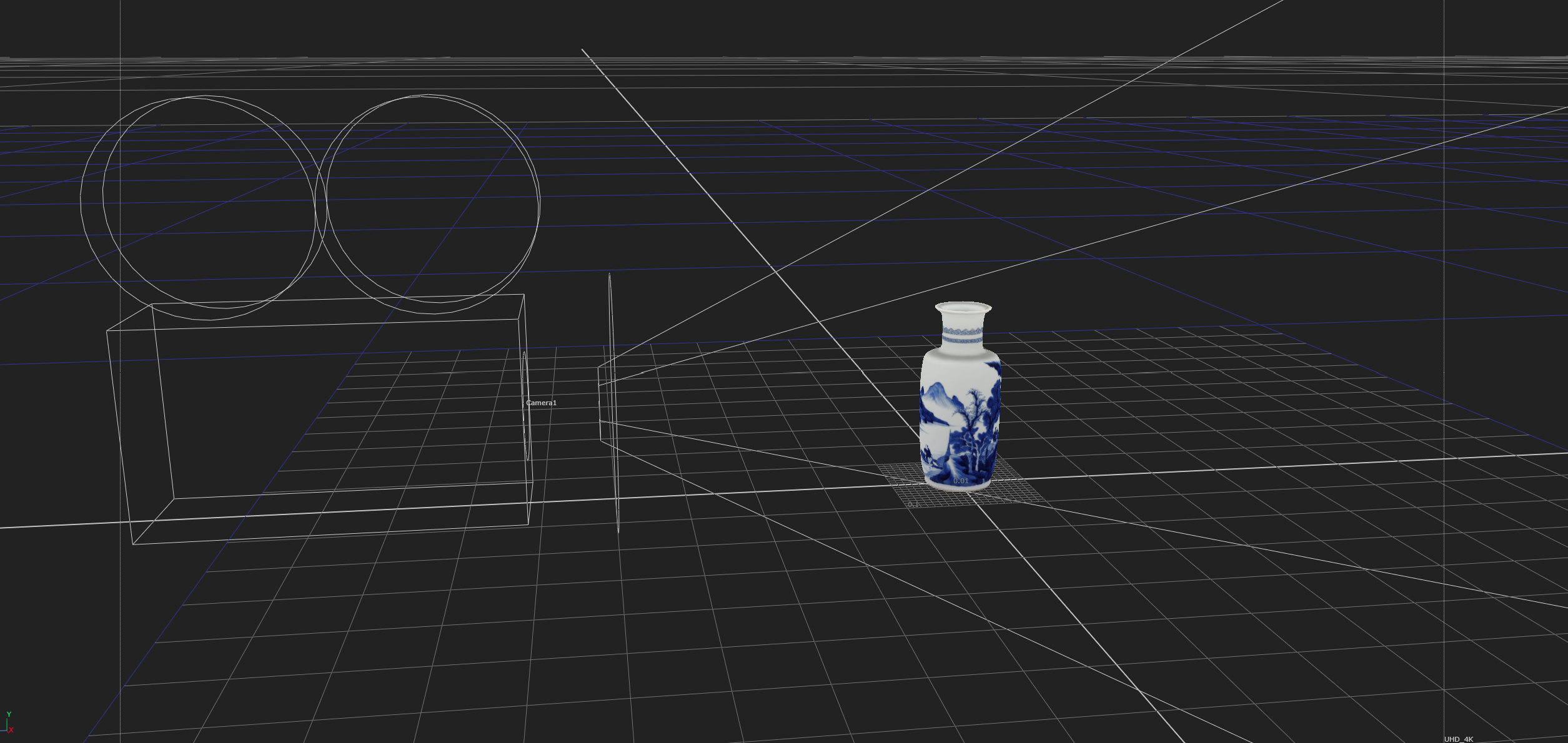
A fully textured vase in a 3D scene.
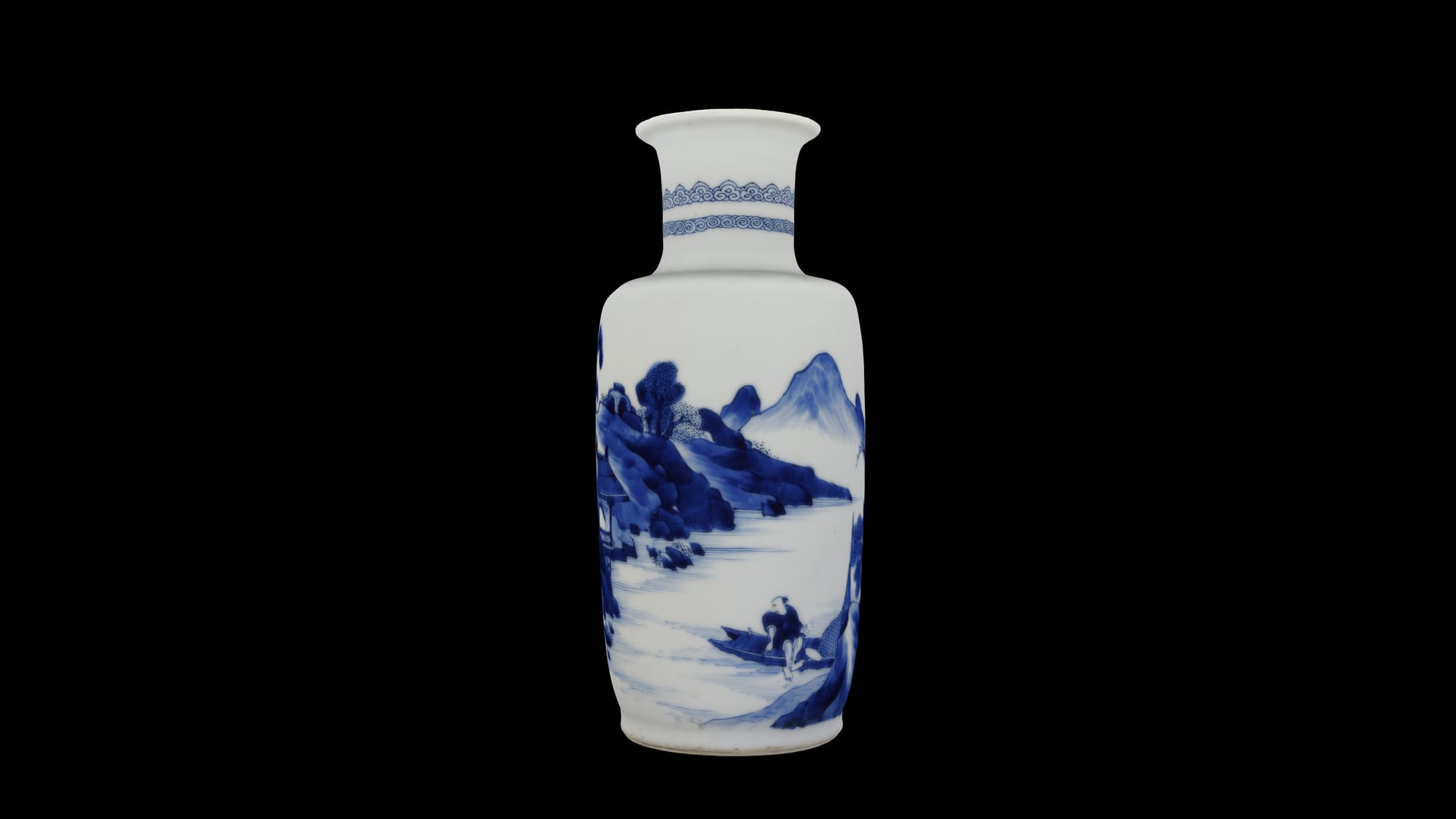
The fully textured vase, rendered from the front.
We can move the camera around in the scene and look at the vase from the side:
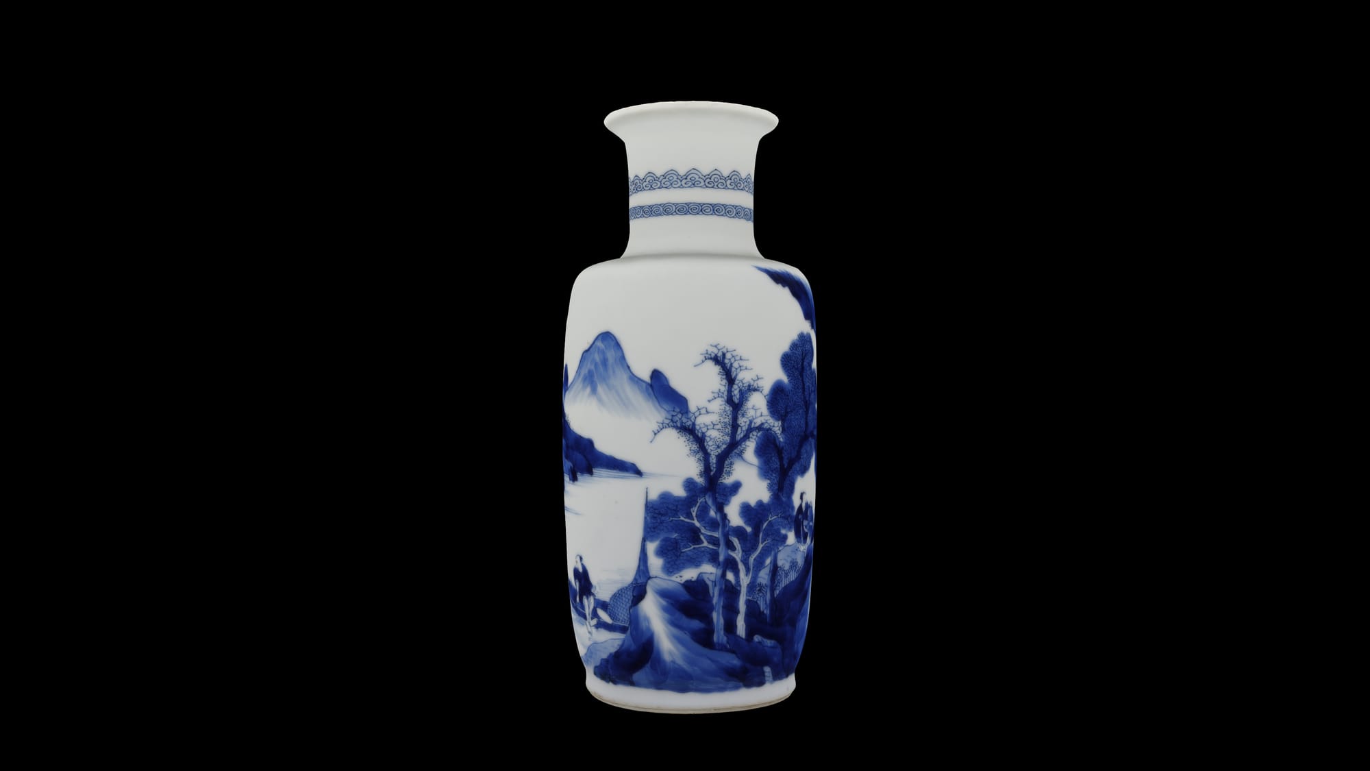
The fully textured vase, rendered from the side.
Now, let’s project the first rendered image (the vase from the front) back onto the same vase geometry using the same render camera (the one from the front) as the projector.
When rendered from the original render camera, the projection looks identical to the original render (minus a miniscule filter hit):
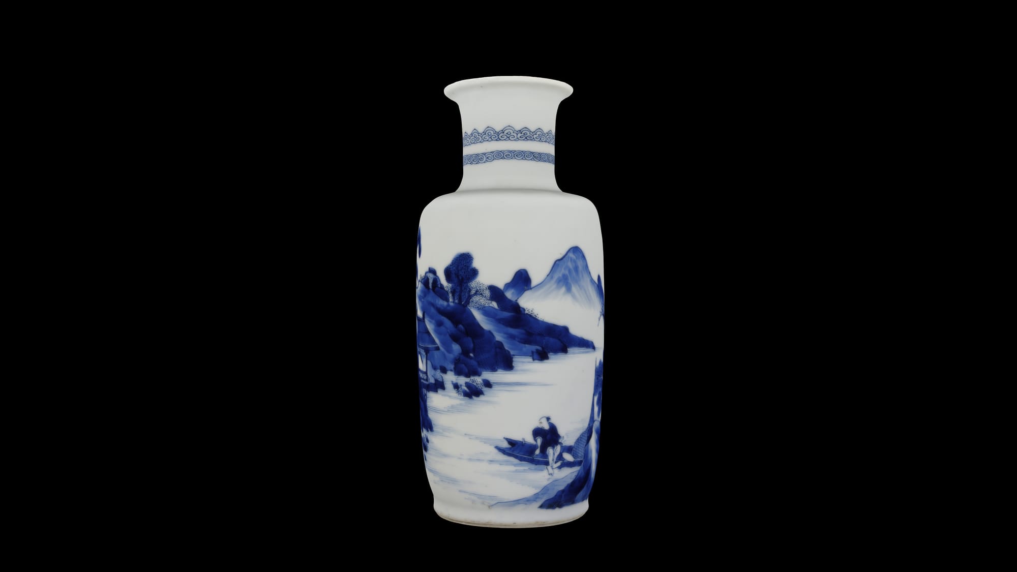
The vase with the projected image on it, rendered from the front. This looks pretty much identical to the original render of the fully textured vase from the front.
However, when we now start to move the render camera around in the scene, you can see that we have lost all the 3D information that was not captured from the original viewpoint:
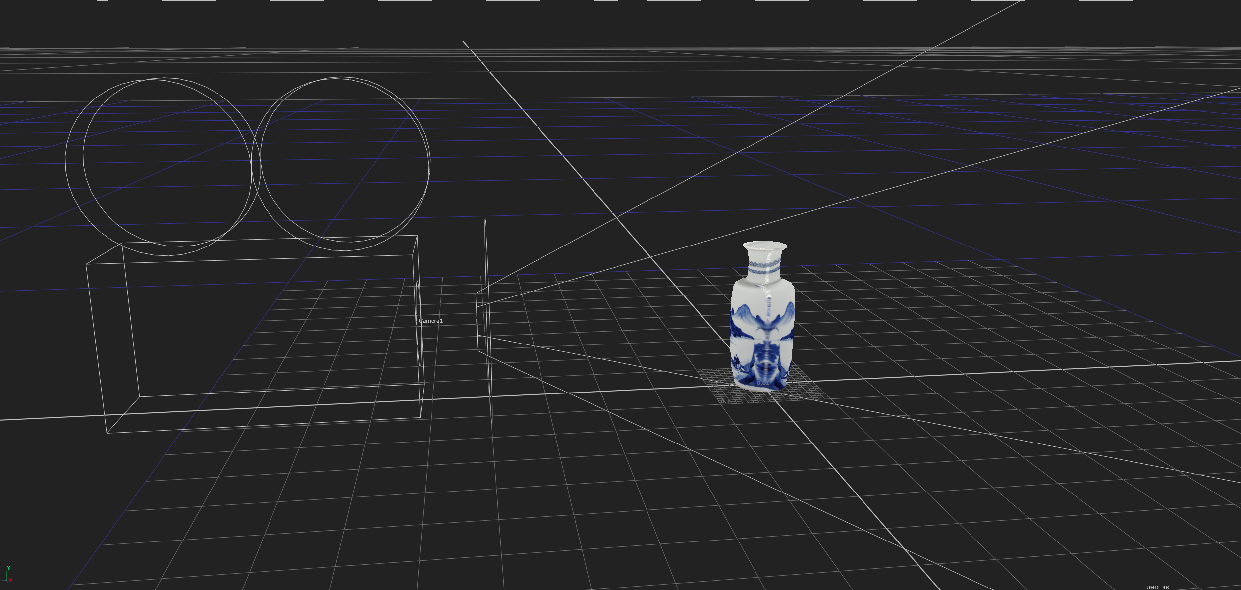
The vase with the projected image on it in the 3D scene. Notice that the pixels on the side of the vase are stretched, and that the back of the vase is now just a duplicate of the front.
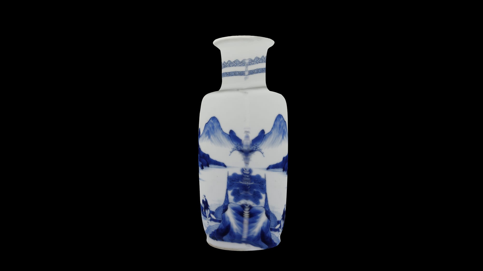
Rendered from the side, we can see that the vase with the projected image on it no longer has the original imagery on its side and back that we saw on the fully textured vase, only stretched or duplicate pixels from the front on view.
This is a limitation of (using a single) camera projection.
Only the surfaces of the objects in the 3D scene that are facing the projector will receive (the most) useful image data projected onto them.
Surfaces that are perpendicular to the projector will just receive smeared pixel values from the thin sliver of the 2D image that hits the edges of the object from the front (i.e. those facing the projector).
And, surfaces that are facing away from the projector will receive either duplicate pixel values from the front facing surfaces, or nothing, depending on your settings.
– And so, in the same way as with the flat 2D image described at the start of this chapter, you still won’t be able to see what’s around a corner (or see a side of an object that’s not facing the camera) in the 3D scene when looking at an object which has a projected image on it. There will just be stretched or duplicate pixels there.
However, even with this clear limitation, camera projections are still extremely useful, and can often convincingly mimic the look of a three-dimensional scene. Especially, when the render camera doesn’t stray too far away from the viewpoint of the projection(s).
You can project any 2D images, whether they are real footage or CG renders. However, in order to correctly align the projections to the 3D scene, there’s an extra hurdle we have to deal with:
Lens Distortion
To complicate things a little bit, real camera lenses distort the captured scene through the various layers of glass inside the lens, and so real footage has lens distortion.
But CG cameras (which have mathematically ‘perfect’ lenses) do not distort the 3D scene, and so CG renders lack lens distortion.
Which means, when you want to project real footage into a 3D scene, you first have to undistort the footage that you’re projecting so that it will line up correctly with the mathematically ‘perfect’ geometry (read: with no lens distortion) in the scene. (As mentioned above, CG renders don’t have lens distortion and so they should not be undistorted before the projection, only footage which contains lens distortion should be).
And then, to line up the output of this mathematically ‘perfect’ projection (whether undistorted real footage or non-distorted CG renders) with real (i.e. distorted) footage again, you have to apply lens distortion to the output of the projection.
Different lenses produce unique lens distortions, and so each real footage that you project has to be undistorted using the lens undistortion information of the lens that captured that specific footage.
And each projection output has to be distorted using the lens distortion information of the lens that captured the footage that your projection is being composited with.
For example, if you have two scans, A and B, and you want to project a patch from scan A and composite it into scan B, you would typically:
- Undistort scan A using scan A’s lens undistortion, and make the patch.
- Project the patch (making sure to render the projection with scan B’s camera) and distort the output using scan B’s lens distortion.
- Merge the result over scan B.
Let’s take a look at a general projection setup in Nuke to make it more visual:
General Projection Setup
We’ll look at specific examples and exceptions a little bit later in the guide, but a general projection setup in Nuke will roughly have the following components:
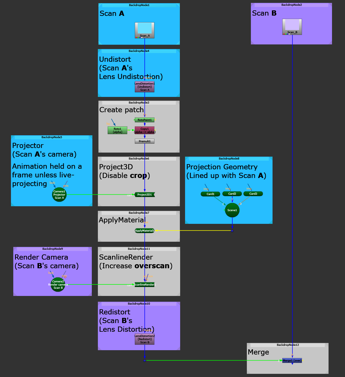
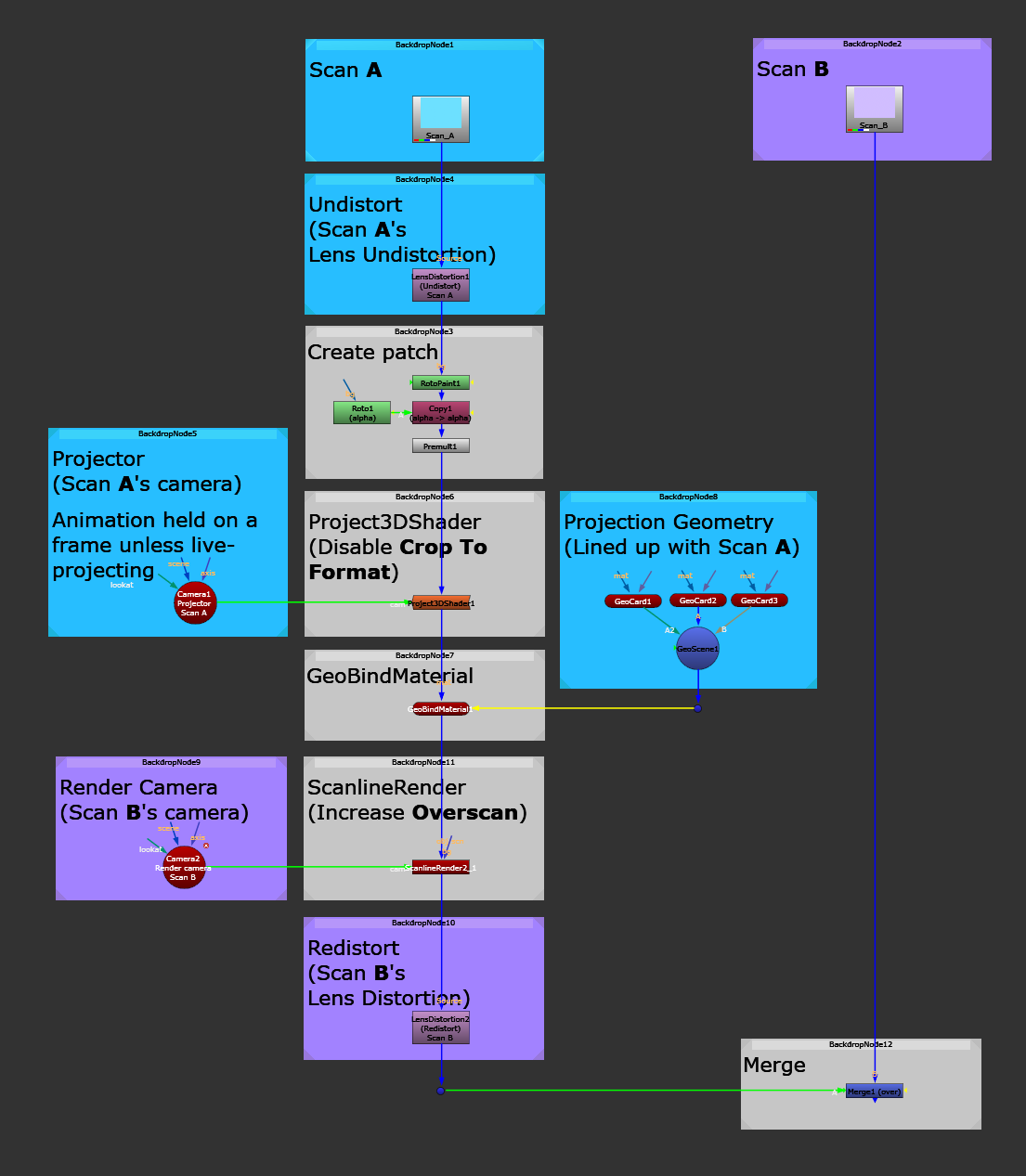
A general projection setup in Nuke, using the classic 3D system (left) and the new 3D system (right).
We’ll take a closer look at each component of the general projection setup, but before we move on, let’s look at the recent updates to Nuke’s 3D system for those who might only be familiar with the classic system:
Nuke’s New 3D System
Back in Nuke 14, Foundry introduced a beta release of a new USD-based 3D system.
And now, in Nuke 17, that new 3D system has officially been moved out of beta and into a production-ready state.
The classic 3D system with the green nodes (currently more widely used) remains available, but you can easily convert any classic setups to the new system.
This video shows how:
3D Projections in Nuke 17: Transitioning from Classic to the New 3D System
To sum up, you can replace all the following nodes from the classic 3D system with the corresponding ones from the new 3D system:
- CameraTrackerPointCloud → GeoCameraTrackerPoints
- Card → GeoCard
- MergeGeo → GeoMerge
- TransformGeo → GeoTransform
- ApplyMaterial → GeoBindMaterial
- Camera [classic] → Camera
- Scene → GeoScene
- ScanlineRender [classic] → ScanlineRender
- Project3D → Project3DShader
- MergeMat → MergeLayerShader
- UVProject → GeoProjectUV
There are also more examples, like Sphere → GeoSphere, Cube → GeoCube, DisplaceGeo → GeoDisplace, or PointCloudGenerator → GeoGeneratePoints. Here is a full comparison between the classic and the new 3D nodes, and here is also a full list of all the new 3D nodes (there are no equivalent classic 3D nodes to many of the new 3D nodes).
All the new 3D nodes now live in the 3D menu in Nuke, while the classic ones live in the 3D Classic menu. Either check the comparison link above, or simply have a look in the new menu if you’re searching for the equivalent to an old node – it’s typically named something similar to before.
Please note that for the rest of this guide, I will list both options when discussing a 3D node or its settings (unless they’re named the same), or when showing a projection setup – with the classic (familiar) 3D node, setting, or setup listed first, and the new ones listed after, like this: Card/GeoCard or crop/Crop To Format. (And you already saw above what it looked like with the two screenshots of the classic and the new general projection setup next to each other).
Okay, let’s go through each component of the general projection setup:
Projection Image
The projection image is what gets projected out from the projector and into the 3D scene.
This can for example be a scan, a matte painting, a CG render, 2D elements such as smoke or fire, a patch, motion graphics, or anything else that’s either a still image or an image sequence.
(In the general projection setup above, it would be Scan A).
As mentioned in the Lens Distortion chapter earlier, before we project the image we have to prepare it for correct alignment with the 3D scene:
Applying Undistortion
The projection image should be undistorted using the lens undistortion information from the camera which shot the image.
(In the general projection setup above, this would be Scan A’s lens undistortion).
But remember if you’re projecting a CG render, the CG is already ‘undistorted’ – or, more accurately: non-distorted. I.e. it doesn’t have any distortion applied to it by default. So you wouldn’t apply an undistortion to a CG render before projecting it, as that would distort the image inversely. The same applies to matte paintings and other elements which may already be undistorted (make sure to check).
– So, only undistort real footage and other elements which actually contain lens distortion.
Next on the list for preparing the projection image is undoing any transformations that may have been applied to it:
Reversing Additional Transformations
Always check for any additional transformations that may have been applied to the projection image.
For example, when working with matte paintings, keep in mind that the matte painter will often grab a still frame of the scan, undistort it, and scale up the image format and/or add overscan to it, before painting up the frame in for example Photoshop.
If so, make sure to reverse any of the transformations that were applied to the scan before it was painted over by the matte painter, before projecting the matte painting. Otherwise, it won’t line up with the scan.
For example, let’s say that the matte painter scales up the image format by 25% to paint in more detail, and also adds another 20% overscan on top so that the matte painting projection can be filmed with an animated camera in comp.
The matte painter might use the following nodes and settings:
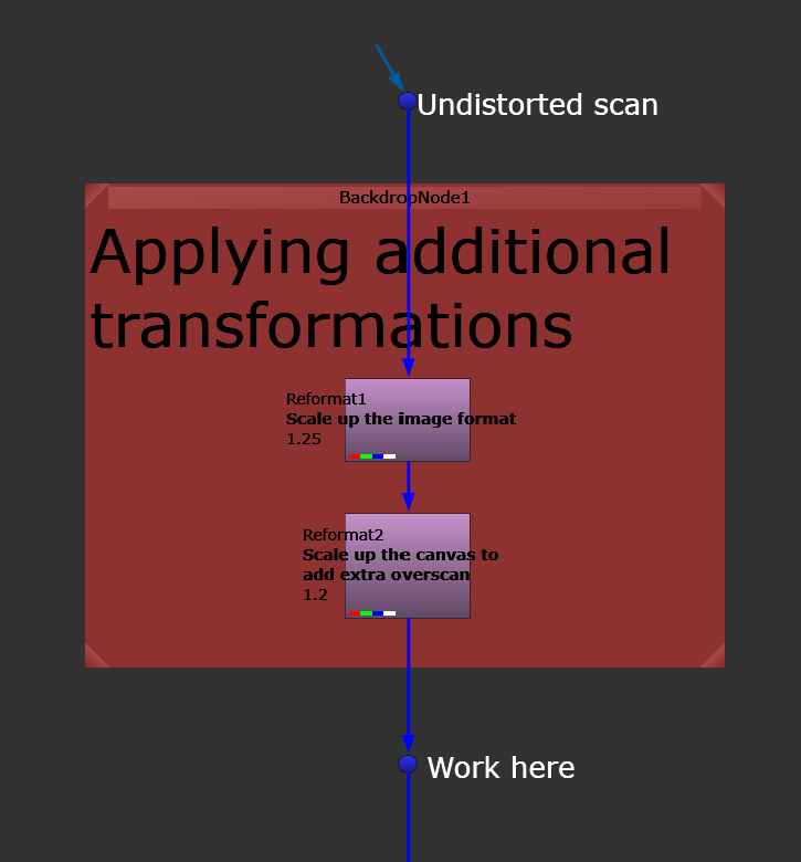
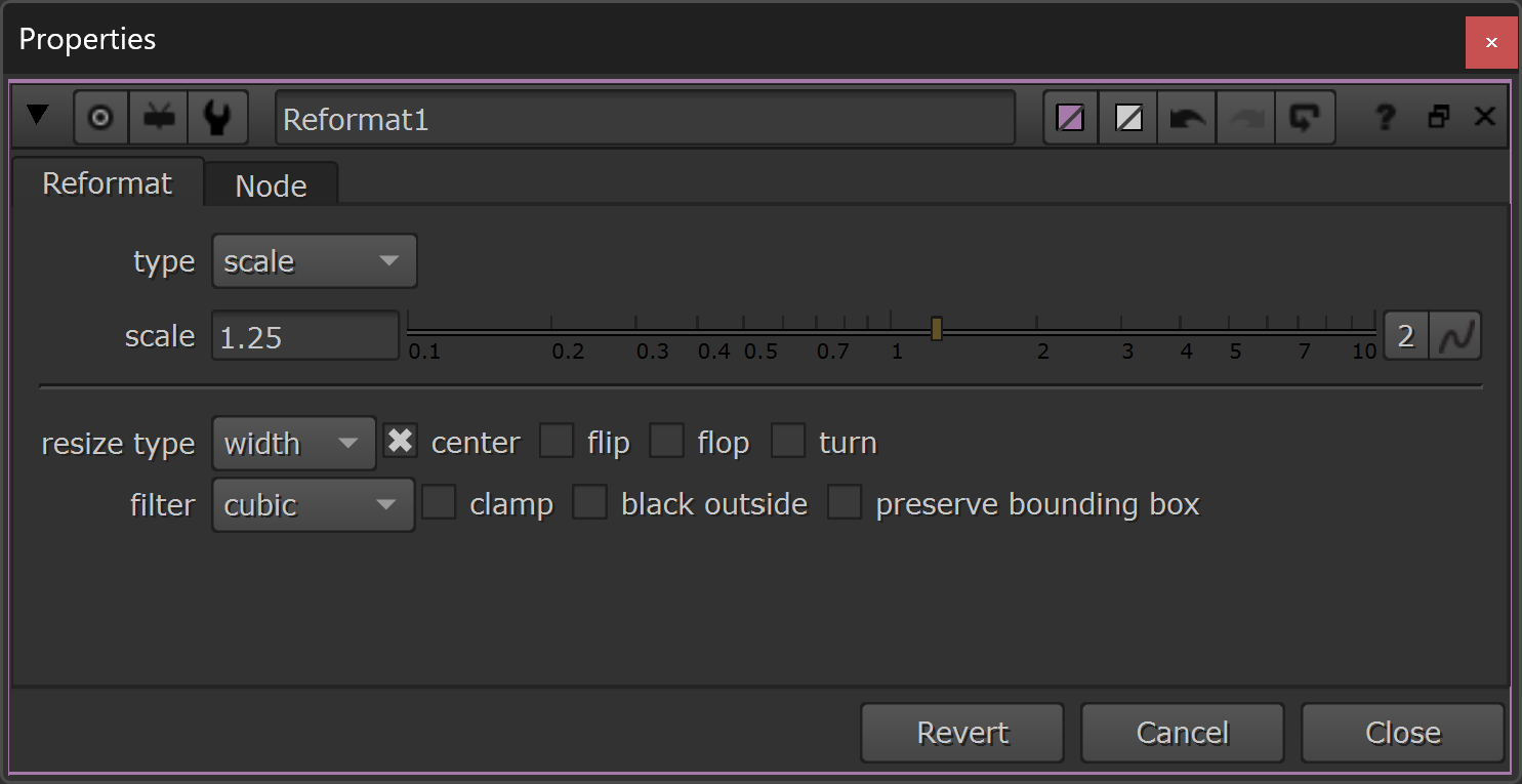
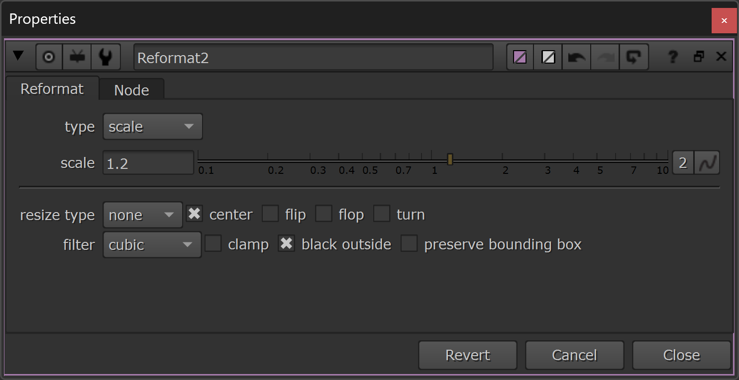
Scaling up and adding overscan to an image, in preparation for matte painting work.
Then, the matte painter goes off into for example Photoshop and paints up the image. And when you receive the finished matte painting to use in comp, you’ll have to reverse those transformations:
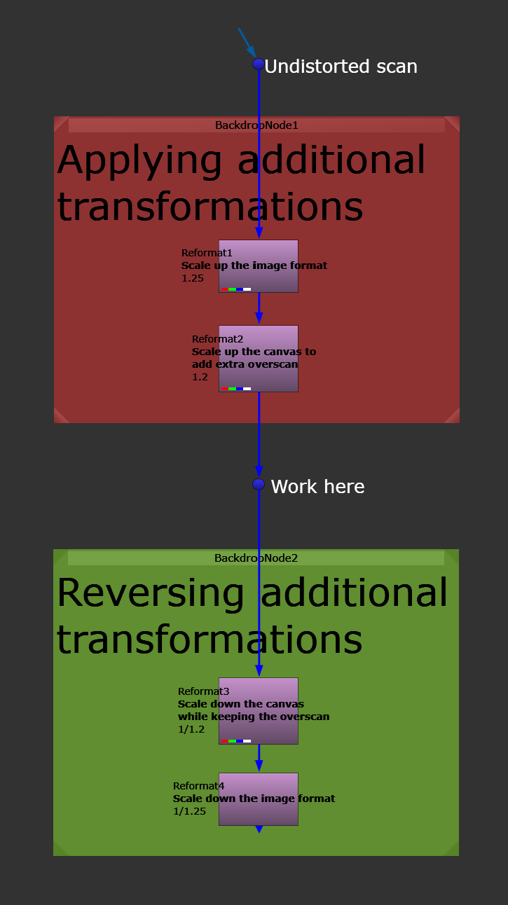
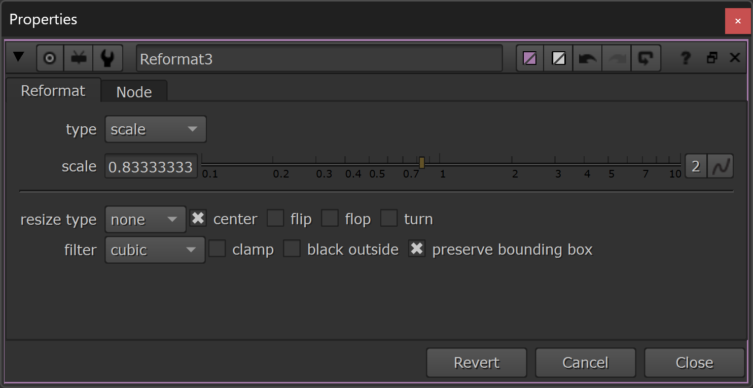
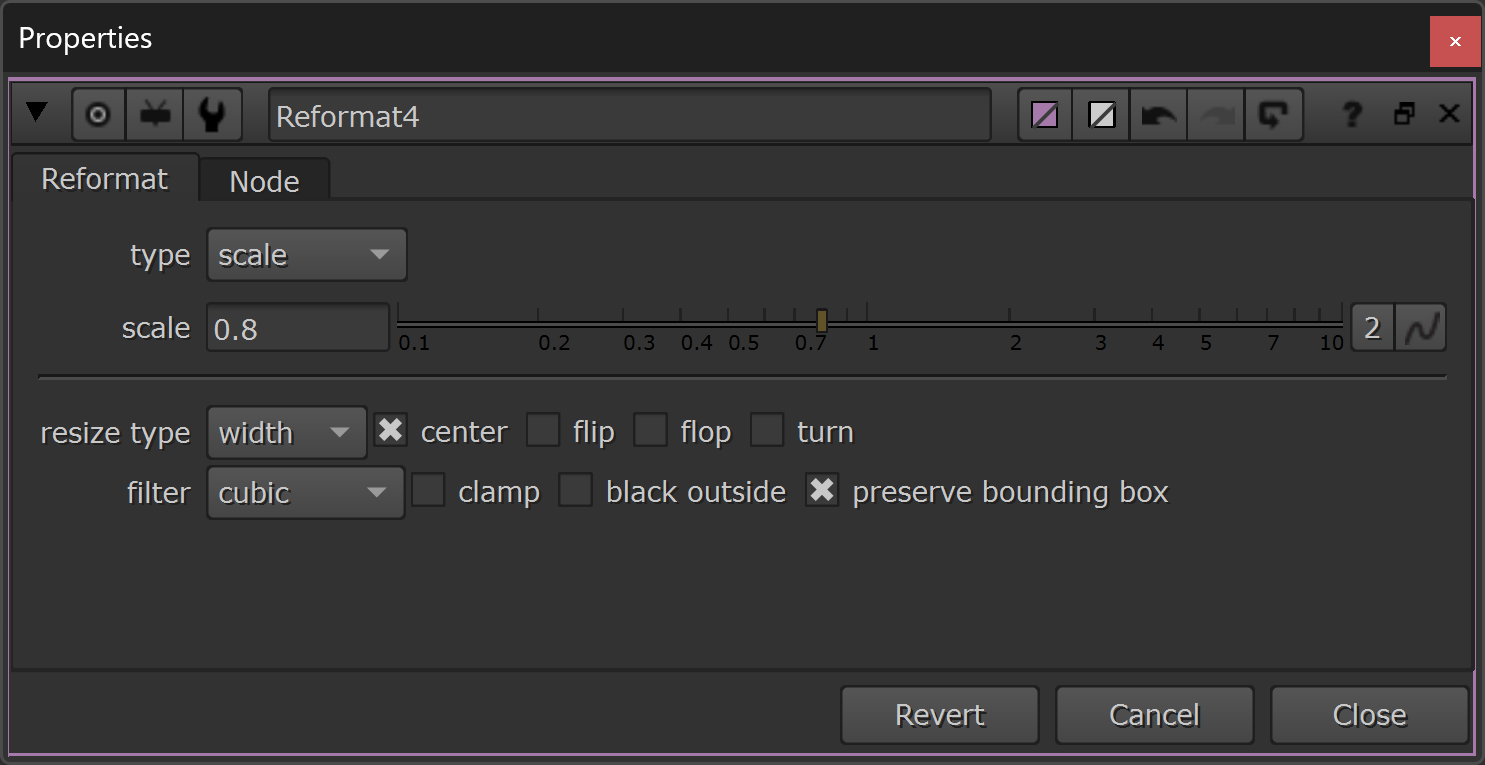
Reversing the additional transformations that the matte painter applied to the image.
Notice the specific settings in each Reformat node, and the specific order of the Reformats to correctly reverse the transformations:
The upscaling and downscaling Reformats (Reformat1 and Reformat4) use the inverse scale value of each other: 1.25 upscale, and 1/1.25 = 0.8 downscale. They also both have the resize type set to width, and the center checkbox ticked for scaling up and down the image format.
The other two Reformats which deal with the overscan (Reformat2 and Reformat3) also use the inverse scale value of each other: 1.2 upscale, and 1/1.2 = 0.83333333 downscale. They both have the resize type set to none, and the center checkbox ticked for scaling up and down the canvas.
In the two Reformats which reverse the transformations (Reformat3 and Reformat4), the preserve bounding box checkbox is ticked to keep the overscan when returning to the original image format.
Now, the matte painting will line up again 1:1 with the original frame of the undistorted scan which it was painted on, plus it has the additional overscan.
And, as long as you don’t put any nodes that break concatenation in between, the projection setup will concatenate with these transformations and preserve the higher resolution details which were painted on the larger scale format.
– I.e. the reverse transformations should go right before the Project3D/Project3DShader node in the general projection setup above.
Next, there is one more thing to do in order to prepare the projection image, but this only applies if the image has overscan and there are cropping issues with the projection:
Bypassing Bounding Box Cropping
Projections in Nuke can become a bit buggy if your projection image has overscan. The output image might get cropped, even if you have turned off any cropping in the setup and are calculating overscan.
When that happens, a way around it is to scale up the canvas of the projection image to encompass the overscan, and compensate for the scaling by adjusting the focal length in the projection camera, which will realign the projection.
(This reformatting would go last, after any reverse transformations, and just before the Project3D/Project3DShader node in the general projection setup above).
With all of the above preparations made, the image is ready for being projected in a technically correct way.
And now, you can creatively work up the projection image, such as doing any paint work, grading, warping, masking of patches, etc.
(E.g. the Create patch Backdrop in the general projection setup above).
Next, let’s take a look at what we’ll be using for projecting the image:
Projector
The projector is the source of the projection, and in Nuke this will be a projection camera in 3D space.
There are two main types of projection:
- Locked off camera projection: The projection camera has no animation, or the animation keys have been killed on a reference frame, or the projection camera has been frameheld on the reference frame.
This is probably the most common way of projecting, and is best for when you are projecting either a still image or an element that has been shot with a locked off camera.
If you’re projecting a single frame matte painting which has been painted on a reference frame of the main scan in your shot, for example, you would framehold (or kill the animation of) the main scan’s matchmove camera on the same reference frame and use that as the projector.
- Live camera projection: The projection camera is animated, i.e. moving around or changing in some other way (e.g. a zoom).
This is for when you are projecting footage (i.e. more than just a still frame) which already has a camera move or lens change in it. If you were to project it using a locked off projector, the projection would just slide all over the geometry, because the camera move/lens change that’s baked into the footage would not be accounted for.
If you’re projecting a scan with a camera move in it in order to film the scan from a different angle, for example, the projector would just be the unaltered, animated matchmove camera for that scan.
Just like how the position and orientation of the camera and the settings of the lens (like the focal length) affect the image that’s being captured, so do the same things affect the image that’s being projected from a projection camera.
If you are projecting for example a scan or a CG render from a different shot, the projection camera’s settings in your shot should match up with the matchmove camera’s or the render camera’s settings in the other shot in order for the projection to line up with the geometry.
Meaning, the camera which filmed the image that you want to project should also be used to project the image – if you want a 1:1 alignment to the original scene.
As I explained in the Projecting Overscan With No Cropping in Nuke guide, the projection camera’s focal length and the projection image’s canvas size are inversely proportional.
If you scale up the canvas size of the projection image (for example to encompass the bounding box in order to avoid cropping issues), you’ll have to inversely scale down the focal length of the projection camera – making it a wider lens to account for the new, enlarged view of the image.
So, if you for instance scaled up the canvas size by a multiple of 1.2, you would divide the focal length by 1.2 in only the projection camera to realign the projection. (The focal length of the render camera would remain the same, only the projection camera would need changing).
Closely linked to both the projection image and to the projection camera is the projection geometry:
Projection Geometry
When projecting a 2D image from a projection camera out into 3D space, there has to be something there for the image to be projected onto in order for us to see the projection. – Something to catch the projected image.
In a movie theatre that would be the silver screen. In Nuke, it can be a Card/GeoCard or any sort of 3D geometry. And the type of geometry that you’ll need for your projection depends on what you’re trying to achieve.
If you’re just adding a simple 2D smoke element into the distance of your shot, a flat card may suffice. But if you’re projecting something which will have more complex parallax, for example a detailed object where the camera is moving around it, you may need more customised geometry.
You could for example get the Matchmove/Layout department to output proxy geometry (a low resolution geometry aligned to the set or the objects in the plate) for you, or you might have received dense and accurate LiDAR scans that were captured on the set. You could even build your own geometry using the ModelBuilder [classic] feature in Nuke.
In addition to matching the general shape and orientation of the object that you are projecting (the more accurate, the better), it’s very important that the projection geometry sits at the right depth in the 3D scene in relation to the camera.
For instance, if a building was 20 metres away from the camera on set during the shoot, but you are projecting a matte painting (for example a top-up for the building) on geometry that is positioned 100 metres away from the matchmoved CG camera, the projection output will likely slide all over the plate building when the (render) camera moves.
So make sure to line up and position the projection geometry as accurately as you can in the 3D scene. See the Positioning Cards/Geometry and Scene Scale chapters in this guide for how to line up projection geometry: Creating Parallax In Nuke.
Here is also a nice technique for accurately placing geometry in 3D space when you have a CG render with a position pass: Snapping Cards To A Position Pass In Nuke.
As mentioned in the parallax guide linked above, a point cloud can be of great help as reference for placing cards or other projection geometry in the scene. But it can also be used to generate the projection geometry:
Using the PointCloudGenerator/GeoGeneratePoints node in Nuke together with your plate and a tracked camera, first create a dense point cloud.
Next, in the Viewer, select the vertices of the point cloud in the area where you want to create projection geometry. Then, make a group from the selected vertices in the Groups tab of the PointCloudGenerator/GeoGeneratePoints node’s properties. Finally, create a mesh from the selected group. This geometry should pretty accurately match up to the shape of the point cloud – which is great for projections.
This video shows the process in action, from around 1:44:
Cleanplate Projections | Nuke Compositing Guide
If your projection geometry is static, you’re ready to move on and project your projection image onto it. However, if your projection geometry is animated, there are a few more steps:
Animated Projection Geometry
If the projection geometry is animated, i.e. it either moves or deforms in 3D space, a regular projection will slip right off its surface as the geometry changes.
– The geometry will move through the projection.
For instance, if you were to hold your hand out in front of a movie screen, a part of the projected image would shine on your hand. But if you moved your hand, a different part of the projected image would shine on your hand. The projection stayed the same while your hand moved through it.
The same happens with regular projections in Nuke when the projection geometry moves but the projection itself stays the same.
But, in theory, if you also moved the projector in sync with the movement of your hand, you could maintain the same projected image on your hand the whole time.
This is obviously not very practical in real life, but in Nuke’s 3D space we can certainly do that. We could for example export a locator (an Axis node) parented to the animated object from Maya/Blender/etc., and connect the Axis node to the axis input of the projection camera.
Now, the projection camera would be locked onto the animated geometry and the projection would stick to it.
It gets a little bit more complicated when the projection geometry deforms, as it’s much trickier to deform the projection image to match up to the geometry deformation. And, parenting the camera to the animation only works for transformations, not for deformations. (We can move the camera and lens around, but we can’t really warp them).
However, another way to make a projection stick to an animated object, which works for both transformations and for deformations, is to make use of the object’s UVs: two-dimensional texture coordinates that correspond with the vertex information of the geometry. This lets us attach pixels to the object which will follow any movement/deformation of the object.
We can do that by taking advantage of the uv/UV Unwrap projection mode in the classic/new ScanlineRender node, by using the UVProject/GeoProjectUV node, or by using a Pref AOV – see Example Use Case 6 in the Example Use Cases chapter, the UVProject/GeoProjectUV chapter, and the P Projection chapter, respectively, for how to do that.
Next, let’s look at a small pitfall to avoid when it comes to projection geometry:
Reflections
Reflections are a bit of a special case, because when you project reflections, the projection geometry should not align with the surface that is reflecting the image.
Reflections are on a different plane to the object that is reflecting them, and should not stick to the object.
If you look at a flat mirror, for example, the distance between the mirror’s surface and your virtual reflection behind the mirror is the same as the distance between you and the mirror surface. I.e. you are looking at a reflection that is twice the distance away from you to the mirror surface.
This video explains how it works:
Mirrors | Optics | 23.1 General Physics
That means if you want to fake a reflection by projecting an image, the projection geometry has to be positioned behind the surface of the reflecting object in 3D space. Otherwise the reflection will look like a picture stuck onto the object, and won’t move like how a reflection would move when the camera moves around.
It’s best to create reflections properly, though, and this video goes over some great tips for that:
Compositing of Reflections
Next, let’s actually perform the projection:
Project3D/Project3DShader
When you have a (preferably) undistorted and prepared projection image, a projection camera, and some aligned projection geometry, the way to connect them all up and actually perform the projection in Nuke is with the Project3D/Project3DShader node:
Create a Project3D/Project3DShader node and connect its main input (in this case, the unlabelled pipe) to the projection image, the cam input to the projection camera, and the output pipe to your projection geometry.
If you have more than one projection geometry node, you can connect them to a Scene/GeoScene node, or to a MergeGeo/GeoMerge node, and use the ApplyMaterial/GeoBindMaterial node to apply the projection to all of the geometry:
Create an ApplyMaterial/GeoBindMaterial node and connect its main input (in this case, the unlabelled pipe) to the Scene/GeoScene or MergeGeo/GeoMerge node, and the mat input to the Project3D/Project3DShader node.
– For reference, see the general projection setup shown earlier.
Now, when you view the projection geometry in 3D space, you’ll see the projection image applied to it – as long as the projection image, the projection camera, and the projection geometry are all aligned.
In the properties panel of the Project3D/Project3DShader node, you have some options available:
- project on: This drop-down menu lets you choose how to project the image onto the geometry: either only onto the front facing side of the geometry in relation to the projection camera (front), only onto the back facing side (back), or onto both sides (both). Since the both option will project the image on both the front and the back of the geometry, you may see a doubling up of the projection at certain angles. If so, you might want to set this option to front or back, depending on which side is facing the projection camera. (However, the issue can still happen with those options, as well, depending on your geometry).
- crop/Crop To Format: Checking this box will extend the input image at its edges with black. If unchecked, the image will be extended with the edge colours. Note that the crop is applied to the input image format, so if you have any overscan in your image it’s best to leave this box unchecked, or you’ll lose the information in the overscan. If you’re getting stretched pixels in your projection, checking this box may get rid of those. However, note that Nuke projections and overscan can sometimes be a bit buggy, and crop issues may still appear – see Projecting Overscan With No Cropping in Nuke for how to fix that.
- occlusion mode: This drop-down menu lets you select options for using raycasting to determine which parts of the object are occluded. The none option means that occlusion is off, the self option tells Project3D/Project3DShader that only the geometry connected to it can cause occlusion, and the world option tells Project3D/Project3DShader that all other objects in the scene can cause occlusion. Normally, I would leave this option set to none because it can often cause artefacts in the projection, and rather use facing ratios for occluding the projection instead – see Combining Projections In Nuke for how to do that.
The Project3DShader node also has two more options:
- Near Plane Clip: When enabled, this will use the Clipping Near value from the connected projection camera’s properties to clip the projection closer than the near-plane distance.
- Far Plane Clip: When enabled, this will use the Clipping Far value from the connected projection camera’s properties to clip the projection farther than the far-plane distance.
By the way, you’re not locked into using a single Project3D/Project3DShader node with a single projection image/camera for each projection geometry. You can combine multiple projections together, for example to project views from different angles and get more coverage.
You can for instance merge multiple projections together with the MergeMat/MergeLayerShader node: Set up two or more Project3D/Project3DShader nodes connected to their own projection images/cameras, and connect them to one or more MergeMat/MergeLayerShader nodes in order to merge the shaders together into one before applying it to the projection geometry.
From here, there are tons of things we can do based on this general projection setup that’s using the Project3D/Project3DShader node, which we’ll take a look at later in the guide in the Example Use Cases chapter.
But first, there is also another node we can use to project images in Nuke, instead of the Project3D/Project3DShader node – just with a slightly different setup. And this other way of projecting comes with added benefits:
UVProject/GeoProjectUV
If you want to animate (move and/or deform) your projection geometry and have the projection image stick to it as opposed to slide over it as the geometry moves/deforms, you can make a slightly different setup using the UVProject/GeoProjectUV node instead of the Project3D/Project3DShader node.
– For example, if you want to add a bit of shape to a flat card in order to get some more parallax in the projection output with your camera move.
The UVProject/GeoProjectUV node is not a shader like the Project3D/Project3DShader node, but instead it modifies the UVs of the geometry. So, rather than projecting the projection image out from the projection camera and applying it to the geometry, it projects UVs onto the geometry to match the projected view and applies the image to the new UVs.
Visually, both results will look identical at first, but the difference is that with the UVProject/GeoProjectUV setup the projection image will stick to the card/geometry as you move/deform it, while with the regular Project3D/Project3DShader setup it won’t.
Let’s compare the two setups, using the example from earlier where we want to add some shape to a flat card:
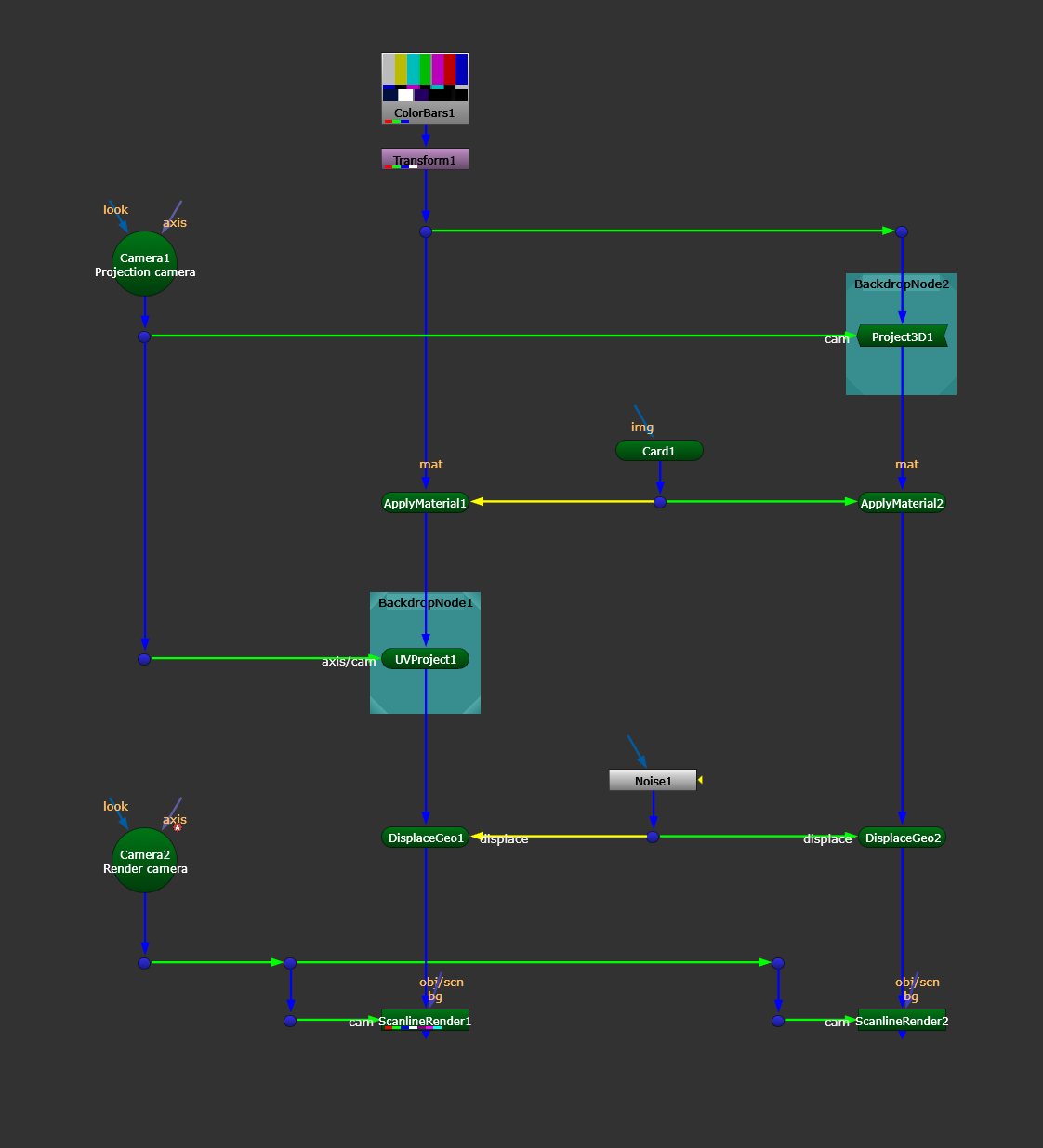
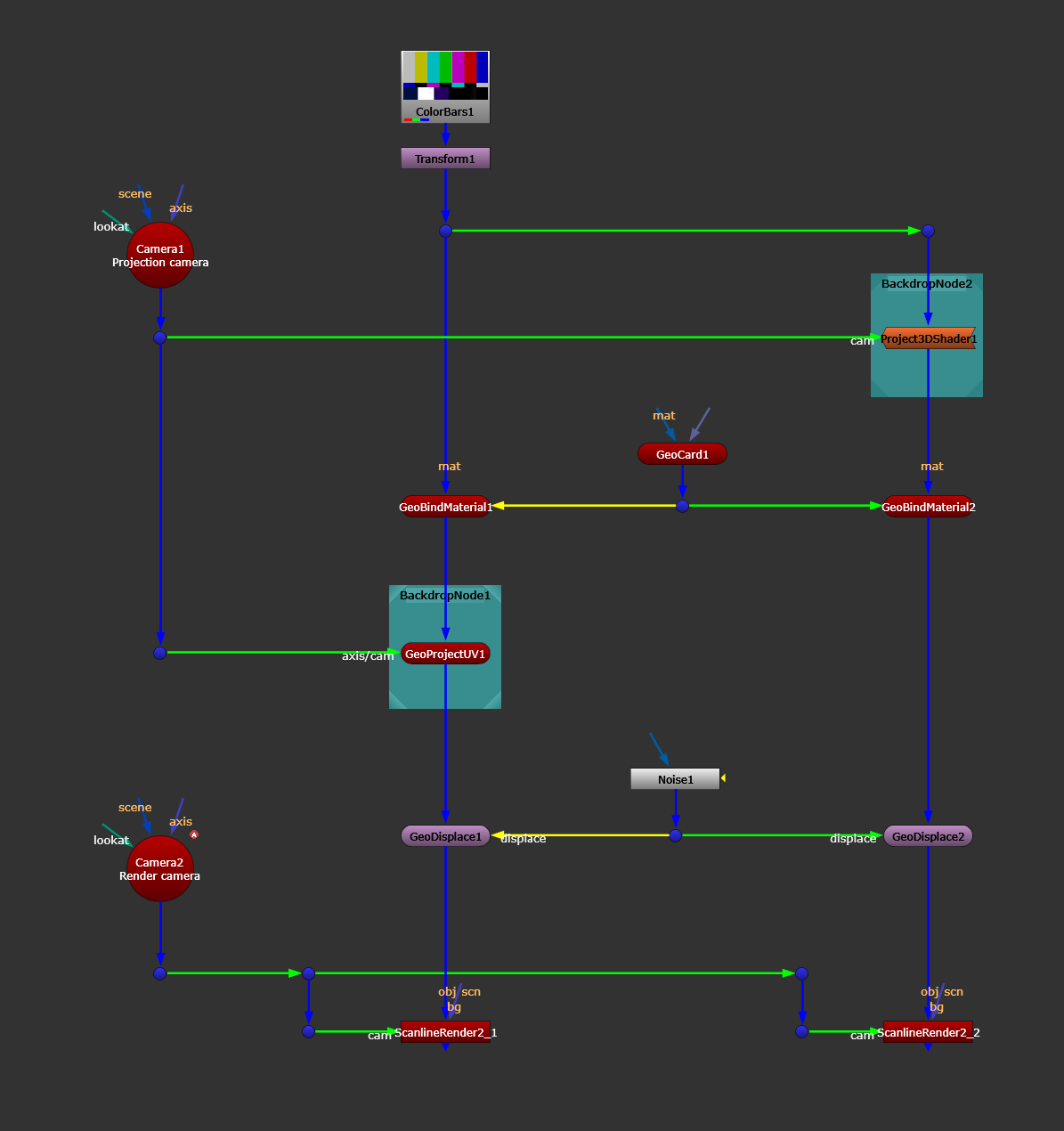
Two projections setups, which are both identical except that one uses the UVProject/GeoProjectUV node and the other uses the Project3D/Project3DShader node – marked with backdrops. Using the classic 3D system for both setups on the left and the new 3D system for both setups on the right.
Notice that if you follow the main pipes, the UVProject/GeoProjectUV node connects upstream to the 3D geometry, while the Project3D/Project3DShader node connects upstream to the 2D texture/projection image.
The order of the UVProject/GeoProjectUV and the ApplyMaterial/GeoBindMaterial nodes doesn’t matter: in addition to the configuration in the pictures above, you can also connect the UVProject/GeoProjectUV node right below the Card/GeoCard node, then followed by the ApplyMaterial/GeoBindMaterial.
The second way might make more sense to you, so feel free to use that. It’s just so that you know that changing the UVs either before or after attaching the texture/projection image will still move the texture/projection image around, regardless.
Without the displacement applied to the geometry (i.e. if you disable the DisplaceGeo/GeoDisplace nodes above), the output of these two setups are identical. But, as soon as we deform the geometry, the difference between the setups becomes apparent.
Let’s take a look at an extreme example: viewing the projection output on the reference frame that we projected on – in this case, where the projection camera and the render camera are identical:
(I’ll crank up the displacement quite high to make it easy to see and understand the differences).
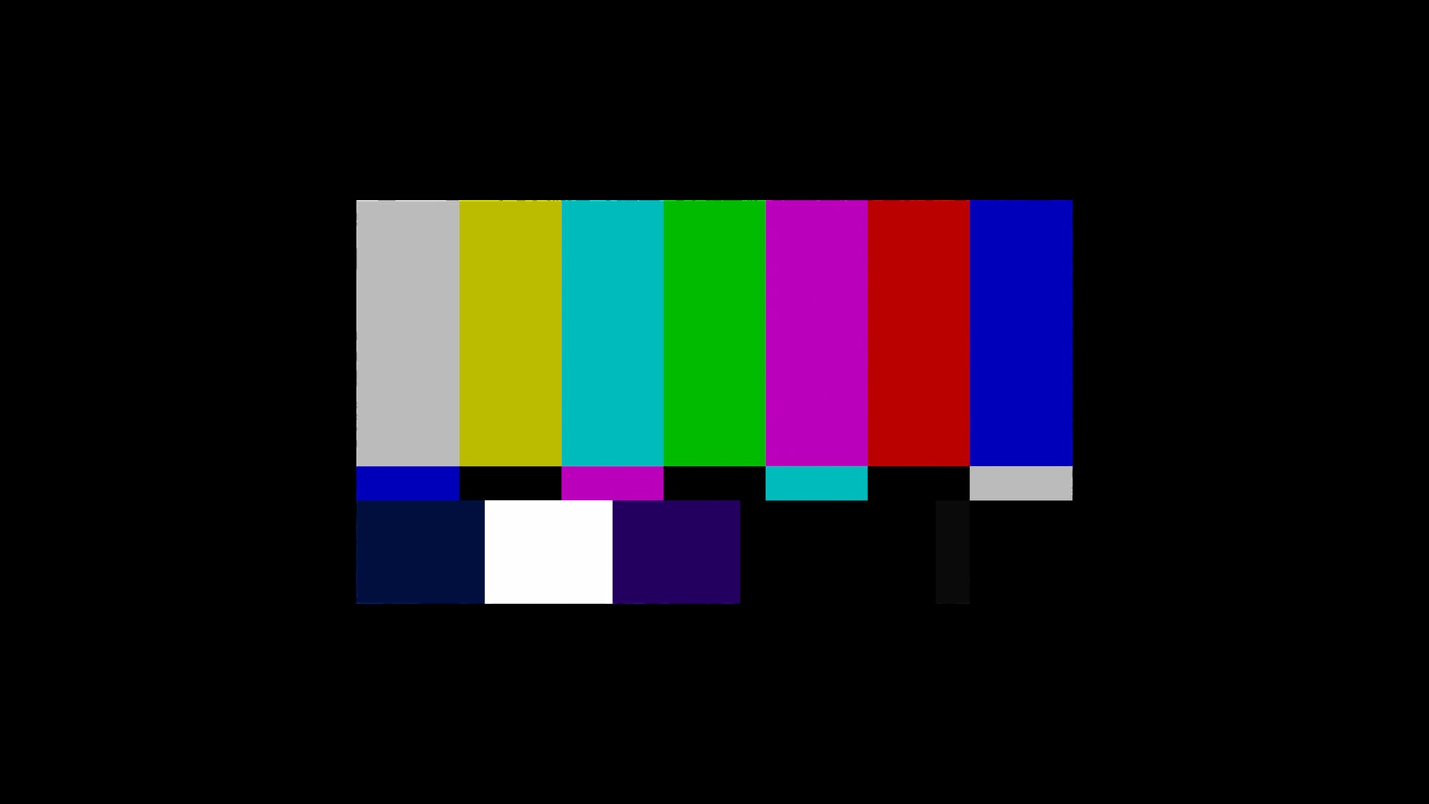
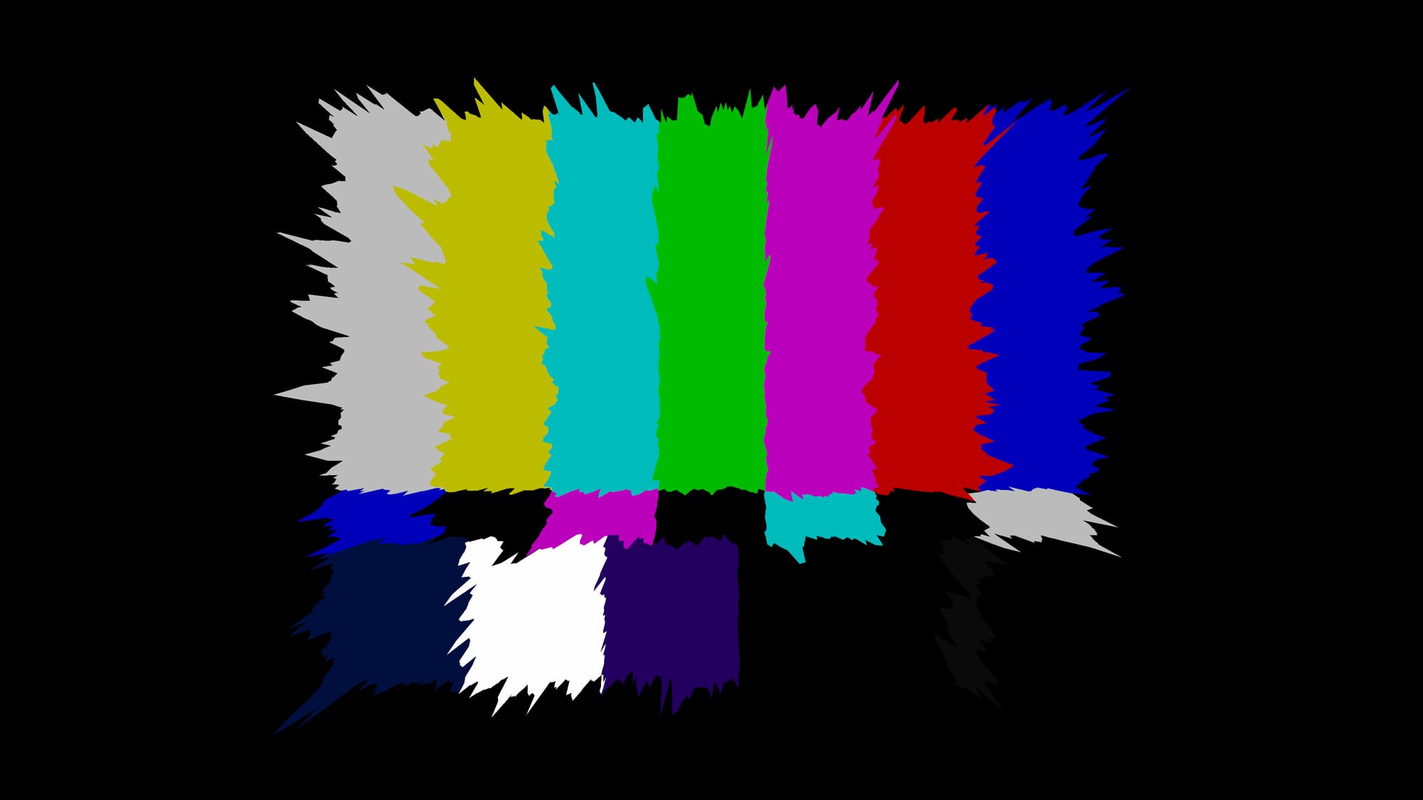
Even though both images are projected onto the same deformed geometry, the output of each projection is very different. Project3D/Project3DShader on the left and UVProject/GeoProjectUV on the right.
The Card/GeoCard is heavily distorted in both setups, as you can see below:
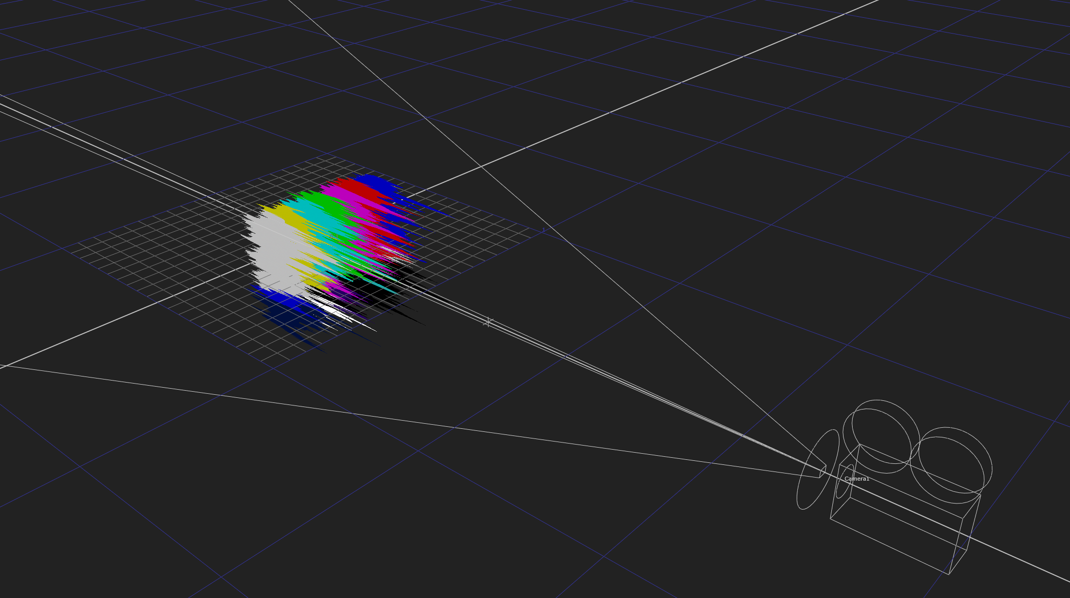
The displacement of the card.
Yet, when using the Project3D/Project3DShader setup, the projection output will (regardless of the projection geometry, as long as it catches the whole projection) look the same as the projection image on the reference frame (if both the projection camera and the render camera are identical on that frame).
Because the projection image is both being projected and captured from the same viewpoint, and the projection image is not attached to the geometry itself, only displayed on it. (Like the example of the hand in front of the movie screen before). Which means, the projection image will just slide over any deforming geometry.
While, with the UVProject/GeoProjectUV setup, the projection image is being attached to the Card/GeoCard first using the Card’s/GeoCard’s original UVs, and then the UVs are being projected to fit the projection camera’s view (making them camera space UVs). The new UVs then replace the original UVs.
(That’s how it’s set up in the configuration pictured above, but you could also attach the projection image directly to the projected UVs if you swap the order around between the UVProject/GeoProjectUV and the ApplyMaterial/GeoBindMaterial nodes. The important thing is that the image is being attached using the new, projected UVs).
Changing the UVs means that you change how the attached image will be mapped onto the geometry. And so, the pixels will still stick to the Card/GeoCard, but now be moved to and locked onto the new UVs, even when the Card/GeoCard is being deformed. Which means, the projection image can be pushed around by the deforming surface of the geometry without sliding.
It’s important to know that with both setups, the projection image has to hit the projection geometry through the view of the projection camera for the projection to work. Meaning, you can’t change/move the Card/GeoCard around before that happens (there’s an exception to this with the new GeoProjectUV node, see further below) or else all of, or a part of, the projection might miss it. – You’d slide the card in and out under the projection.
But, with the UVProject/GeoProjectUV setup, once the projection is hitting the Card/GeoCard (and so the projection image has been attached to the new UVs), you can then deform or move the Card/GeoCard around after the fact with for example a TransformGeo/GeoTransform node, and the projection will stay attached.
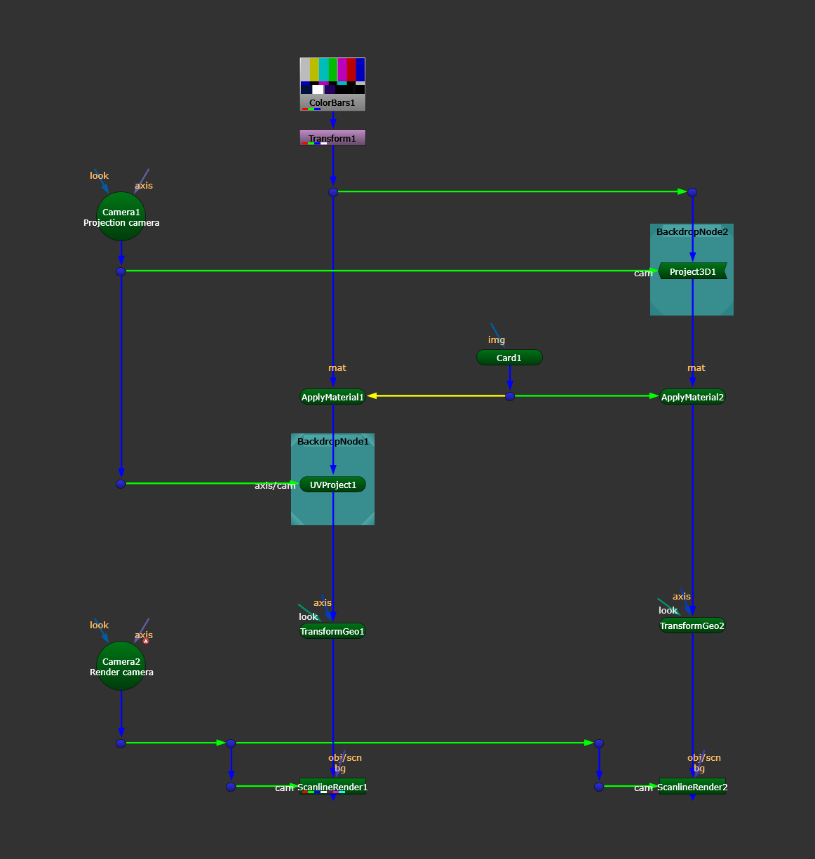
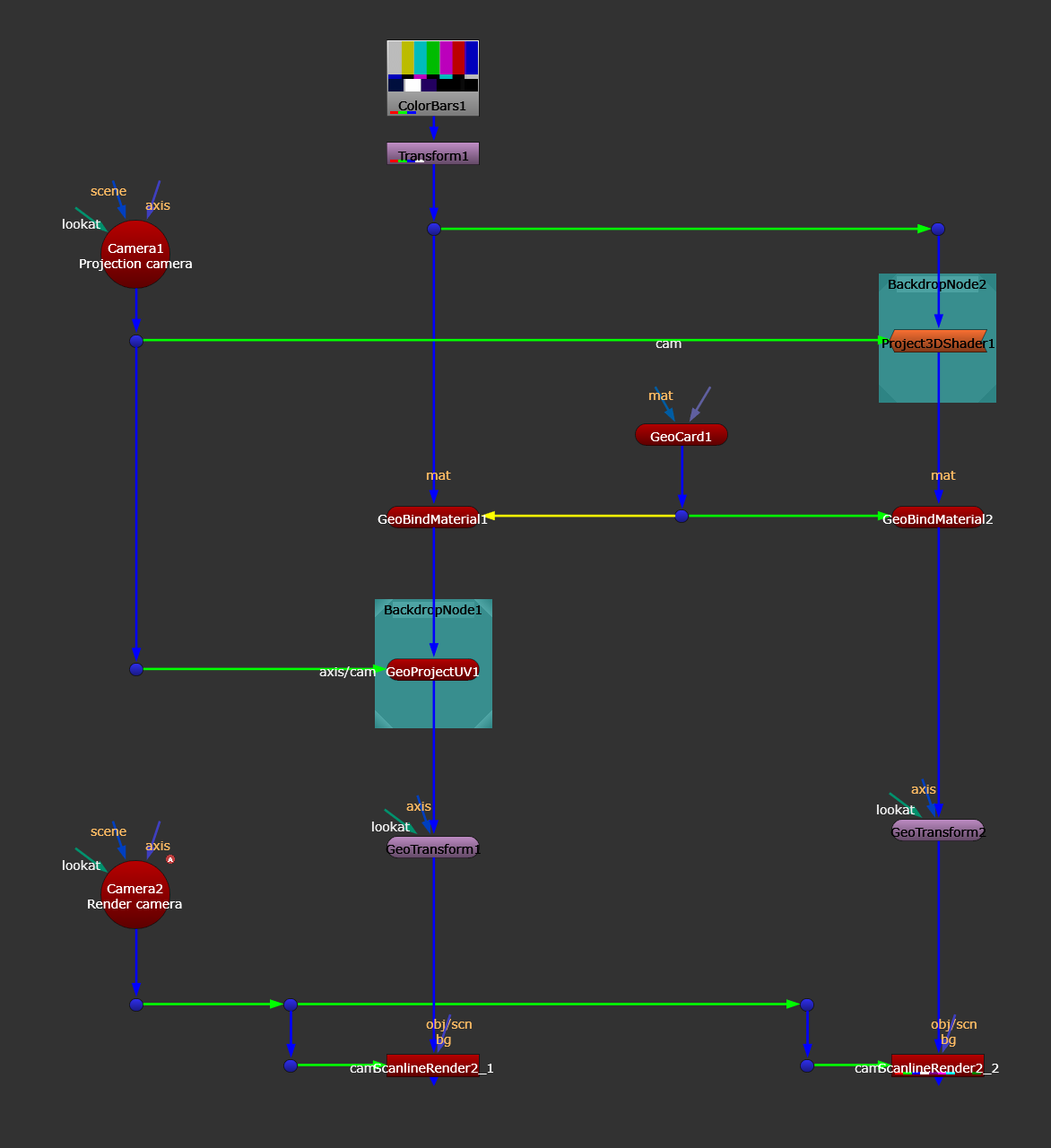
Changing the values in the TransformGeo/GeoTransform node in the setup on the left would make the Card/GeoCard move around in the scene and bring the projection along with it. Changing the values in the TransformGeo/GeoTransform node in the setup on the right would just slide the Card/GeoCard under the projection and nothing would stick. Using the classic 3D system for both setups on the left and the new 3D system for both setups on the right.
This video shows the differences in practice between the Project3D and UVProject setups:
How to use UV Project node in Nuke
There is, however, a little bit more to it, as mentioned above – an exception with the new GeoProjectUV node. This Foundry User Guide shows the differences between UV projections in the new 3D system and the classic system. And, the new GeoProjectUV node has the additional option to set a Reference Frame, which when activated means that the projection will only be applied at the frame that’s being referenced, making it easy to set up projections that stick to animated geometry.
And so, if the geometry is already animated before the GeoProjectUV node, the projection will still stick when using the Reference Frame option in the GeoProjectUV node.
Lastly, if you have a UV pass rendered as part of your CG AOVs, you can also use the STMap node or a tool like UV Projection Sticky for attaching/projecting images onto the scene.
Next, let’s quickly look at what we’ll view the projection(s) through:
Render Camera
The render camera is simply the camera which you want to film the projection through.
This will usually be the matchmove camera for the scan that you’re merging the projection over. (In most cases, it will be your shot’s main scan’s matchmove camera, but it could also be another scan’s matchmove camera. For example, if you’re separately compositing the footage that will go inside of a screen insert in your comp).
This is to ensure that the projection will track with your scan.
But it could also be your own, custom camera to suit your specific needs. For example, if you want to change the camera move, the camera angle, or the focal length of the lens to re-photograph the shot.
In any case, unless you combine multiple projections together and get enough coverage, the render camera should typically not stray too far away from the projection camera. Like we saw with the vase projection earlier, a large change in the render camera’s position will reveal the limitations of a single projection. I.e. you’ll see stretched or duplicated textures.
But, with all of the above in order, it’s time to output the projection:
Projection Output
To output the projection, which currently only exists in 3D space, we have to render the 3D scene into a 2D image.
Nuke has a couple of different native renderers which can do that. Most commonly used is the classic/new ScanlineRender node, but there is also the RayRender [classic] node which can be useful for things like raytracing reflections, generating ambient occlusion, or outputting different AOVs (though the new ScanlineRender node can also do these things). And then there are third-party plug-ins such as the PrmanRender by Pixar (this classic renderer is only available through the GeoRender node in the new 3D system), the VRayRenderer by Chaos, and the OctaneRender by Otoy.
But if you boil it down they essentially all do the same thing, just with different options: they photograph the 3D scene from a render camera to output a 2D image.
Using the classic/new ScanlineRender node or the RayRender node, you would connect your 3D scene, i.e. your projection geometry with your projection image projected onto it, to the obj/scn input, your render camera to the cam input, and (optionally) an image or a format (for example a Reformat node) to the bg input.
In the classic/new ScanlineRender node’s properties, adjust the different Shutter options and the samples/Camera Samples to match the motion blur of the scan that you’re compositing the projection output with.
Also, make sure to increase the overscan value to cover your needs downstream: After the classic/new ScanlineRender node, you would connect your lens distortion node to apply lens distortion to the output of the projection.
By default, the classic/new ScanlineRender node outputs additional layers, like depth and motion vectors. Remember to remove any superfluous layers by connecting a Remove node after the classic/new ScanlineRender node with its operation set to keep, and keeping only the layers that you need.
The classic/new ScanlineRender node also has different projection modes. By default, it’s set to render camera, but another very useful option is the uv/UV Unwrap projection mode.
This will let you output the image unwrapped in UV space. (Make sure to connect a Reformat node set to a square format into the bg input of the classic/new ScanlineRender node to output the UVs correctly).
– Which is great for adjusting texture maps (for instance by projecting images onto CG geometry) and applying them back onto the geometry, and having them stick to the surface as it moves around or deforms. See Example Use Case 6 in the Example Use Cases chapter for more information.
Now, we’ve gone through all the elements of the general projection setup and you should have a pretty good idea of how projections work. Let’s take it further:
Combining Projections
As mentioned earlier in the guide, it’s possible to combine multiple projections together.
This is very useful if a single projection doesn’t give you the coverage that you need for the camera move in your shot. I.e. when the render camera sees a side of an object that the single projection doesn’t hit straight (enough) on, revealing stretched/duplicate pixels and/or a dodgy perspective.
Again, you can combine projections together using the MergeMat/MergeLayerShader node, or use facing ratios to create masks for each projection, and then merge them together: Combining Projections In Nuke.
Next, let’s look at a different way altogether for doing projections:
P Projection
If you want to project something onto a CG render, there is a very useful alternative method for doing the projection called position projection, or P projection for short.
P projections work by converting a position pass to an ST map using a projection camera, and transforming the projection image using the ST map to create a projected image which is wrapped to the shape of the object(s) represented in the position pass.
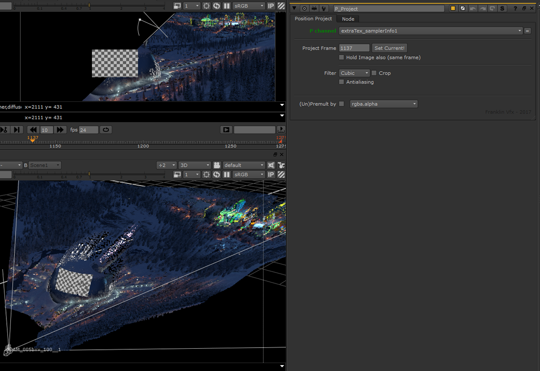
Projecting a checkerboard onto a position pass, visualised with a point cloud. (Source).
This requires a bit of complicated matrix manipulation, but luckily there are many great, ready-made tools available to download and use:
- Position Project by Franklin Toussaint.
- PosProjection by Mark Joey Tang.
- RefPosProject by Riley Gray.
- k_pProjection and k_pStickyProject by Nicolas Gauthier.
- Reproject_3D by Spin VFX (based on ReProject3D by Michael Garrett).
- ProjectionBuddy by Hiram Gifford.
- P2STMap by Peter Mercell (Nuke plugin for performing the same position pass to STMap conversion as in the tools above, but in a more efficient way).
- Triplanar Projection by David Lee-DuVoisin.
There are different types of position passes that you can use for the P projections:
World position (often just called P, Position, or Pworld) are static coordinates, which are great for using to project things onto static objects or onto static areas of the scene.
Reference position (often called Pref) and Object position (often called Po or Pobject), however, stick with the animated objects in the scene, and are great for using to project things onto moving or deforming objects.
Most P projection tools will only support world position passes, as that’s the most common type of position pass used for this type of projection, and projecting onto a reference or object position pass is more complicated to do. But some tools are built to accommodate either, or both – make sure to check if the tool you pick supports the type of projection that you want to do.
Next, let’s look at some practical projection setups and workflows:
Example Use Cases
Let’s go through each of the example use cases for camera projections that were mentioned at the beginning of the guide:
Example Use Case 1:
Re-photographing a shot from a different angle or with a different camera move.
For this type of task, you’ll be using a live camera projection. I.e. the projection camera will be the matchmove camera for the scan that you are projecting. (So that you’re projecting what was captured from the same exact viewpoint).
The more accurate the projection geometry matches the original scene, the better. Normally, you’ll need at least the main parts of the scene, like walls, floor, significant objects, etc. Otherwise, the parallax won’t look right when you render out the scene with a new camera.
An example setup for this use case might look like this:
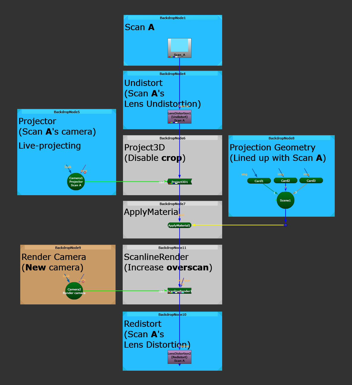
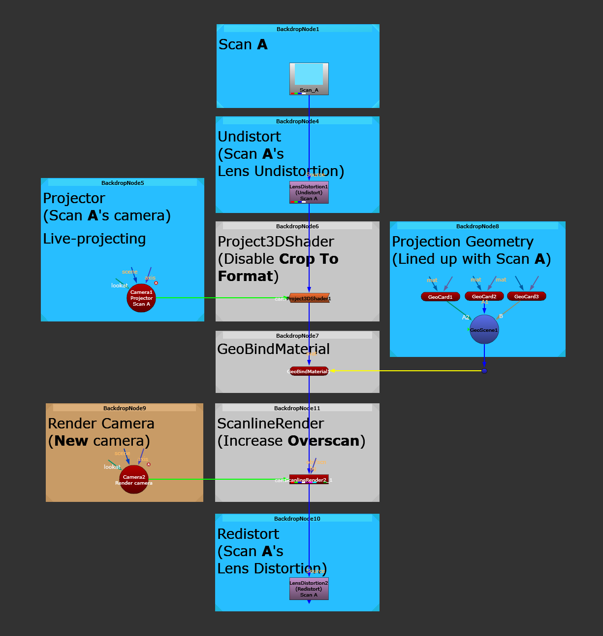
The projection setup for example use case 1.
Example Use Case 2:
Tracking a patch to a shot (for example to do clean up work).
When you are doing clean up work it’s usually a good idea to framehold a frame of the plate, undistort it, paint over it, and project a patch of the cleaned up frame back over the plate.
That’s exactly what’s happening in the general projection setup that was shown earlier in this guide. Here it is again, for reference:
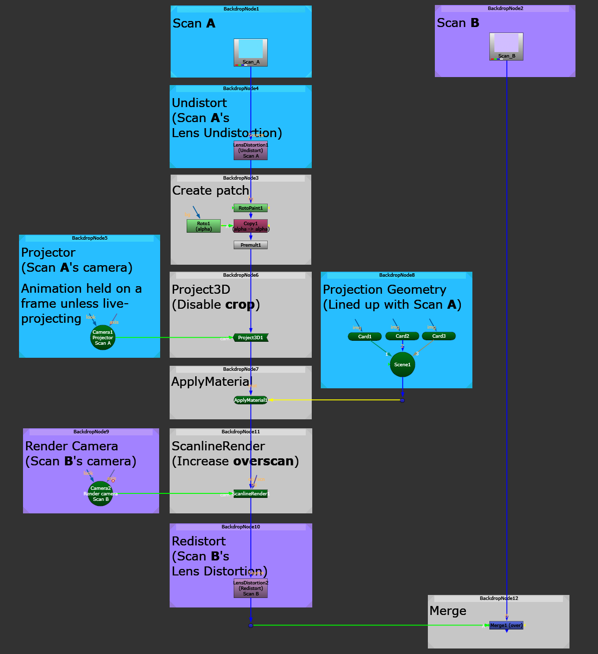
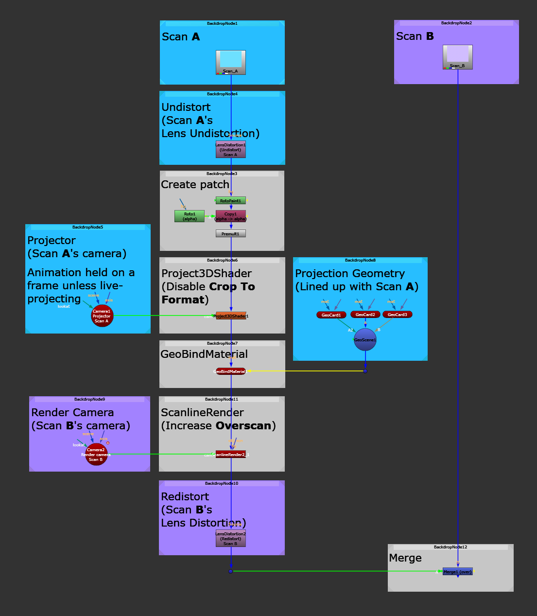
The projection setup for example use case 2, i.e. the general projection setup.
When doing that, it’s best practice to choose the frame from the plate where you see the most detail in the object that you want to paint over, and where it is sharpest, i.e. with the least amount of motion blur and/or defocus.
For example, if there is a street sign which is closer to the camera at the start of the shot than at the end, you would pick a frame from the start of the shot to do the paint work on. That way, the projection will hold up both at the start of the shot and at the end.
If you instead had picked a frame to clean up at the end of the shot, when the sign is small in the frame, the projected sign would likely look pixelated and soft at the start of the shot where the projection would scale up the patch.
– You can scale down something which already has detail and it will still look good, but it’s not as easy to scale up something which lacks detail and have it look good.
Example Use Case 3:
Re-using CG renders or a matte painting from another shot.
If multiple shots in a sequence have similar camera angles looking towards the same part of the environment, it’s often possible to render just one CG render, or paint up just one matte painting (each with a bit of extra overscan), for a hero shot in the sequence, and then reuse the render or matte painting across the other shots.
This is great for saving time, either render time or time spent painting, and also for keeping continuity across a sequence.
I’ve described the method for doing that in this guide: Re-Using CG Renders Across A Sequence In Nuke.
Here is the setup:
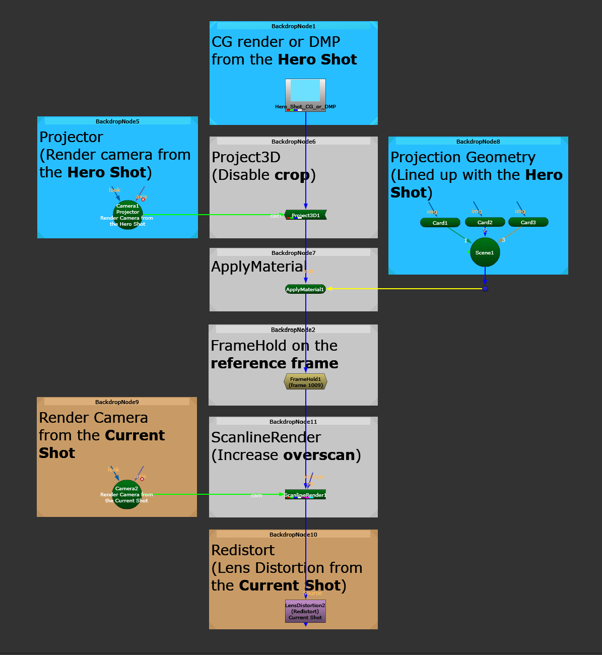
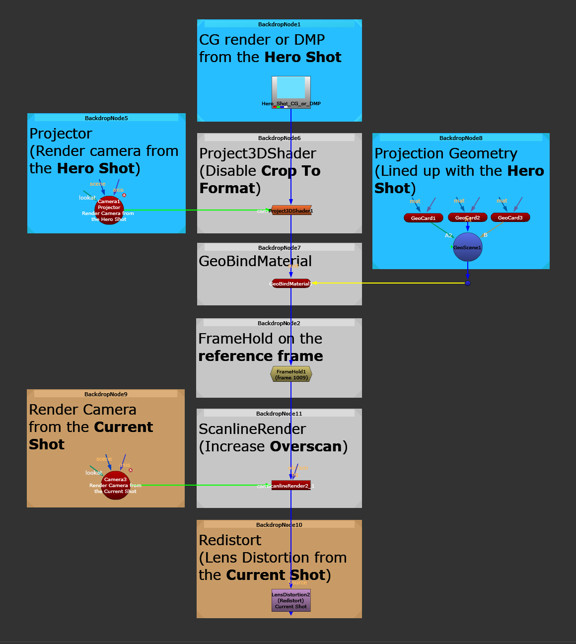
The projection setup for example use case 3.
A couple of key things to notice about this setup:
- The projection camera should be the render camera from the hero shot. You’ll want to project the hero render from the hero camera’s viewpoint to get a 1:1 alignment with the original scene.
- Add a FrameHold node, and set it to hold the projection on the reference frame, meaning the frame that the CG was rendered on (if a single frame was rendered) or the frame that the DMP was painted on. Or, a frame that you choose (if multiple frames were rendered) – if so, pick a frame that most closely matches your current shot’s camera angle.
Example Use Case 4:
Placing 2D elements (smoke, fire, rain, etc.) into a 3D scene.
You don’t really need to project 2D elements onto Cards/GeoCards or other geometry in your 3D scene (although you certainly could if you wanted to). You would normally just put each element straight onto a Card/GeoCard (i.e. attaching the element to the UVs of the Card/GeoCard, meaning you can move the geometry around and the element stays on the geometry).
But this example use case is more about using projection to help integrate the elements that you’ve set up in your 3D scene with your scan – making it feel like the elements are in the scene, and not just composited on top of it.
Let’s for instance say that you have a scan with a person walking in an environment, and you want to composite a bunch of 2D elements like smoke, fire, or rain into the scene. You want the person to feel embedded within the elements – walking within the smoke, between the fires, or within the rain.
First, make a 3D scene with all of the Cards/GeoCards or other geometry (with your elements put on them) laid out in depth where you want to place your elements. And then, output the 3D scene using a ScanlineRender node and your matchmove camera, making sure to apply the lens distortion from the scan.
Merging this output over the scan would just put all of the smoke, etc. on top of the environment and the person, and rotoing the person back over would just put them on top of all of the smoke.
You could separate out the person and project them on a Card/GeoCard placed within your scene between the elements, but undistorting the scan and outputting the person through a ScanlineRender node means taking a filter hit, softening your scan. Instead, it’s better to live-project the roto onto a Card/GeoCard placed within your scene in between the elements, and use the result as a Deep holdout.
Let’s see how that works:
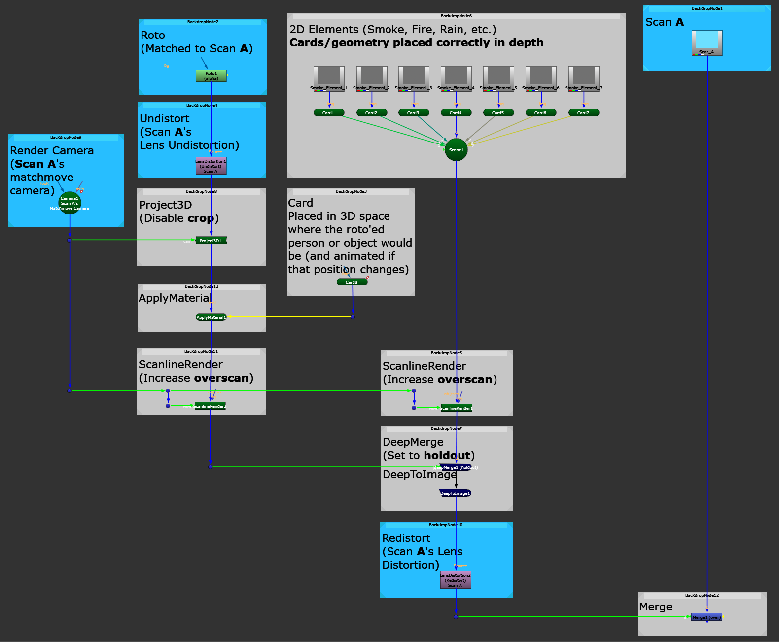
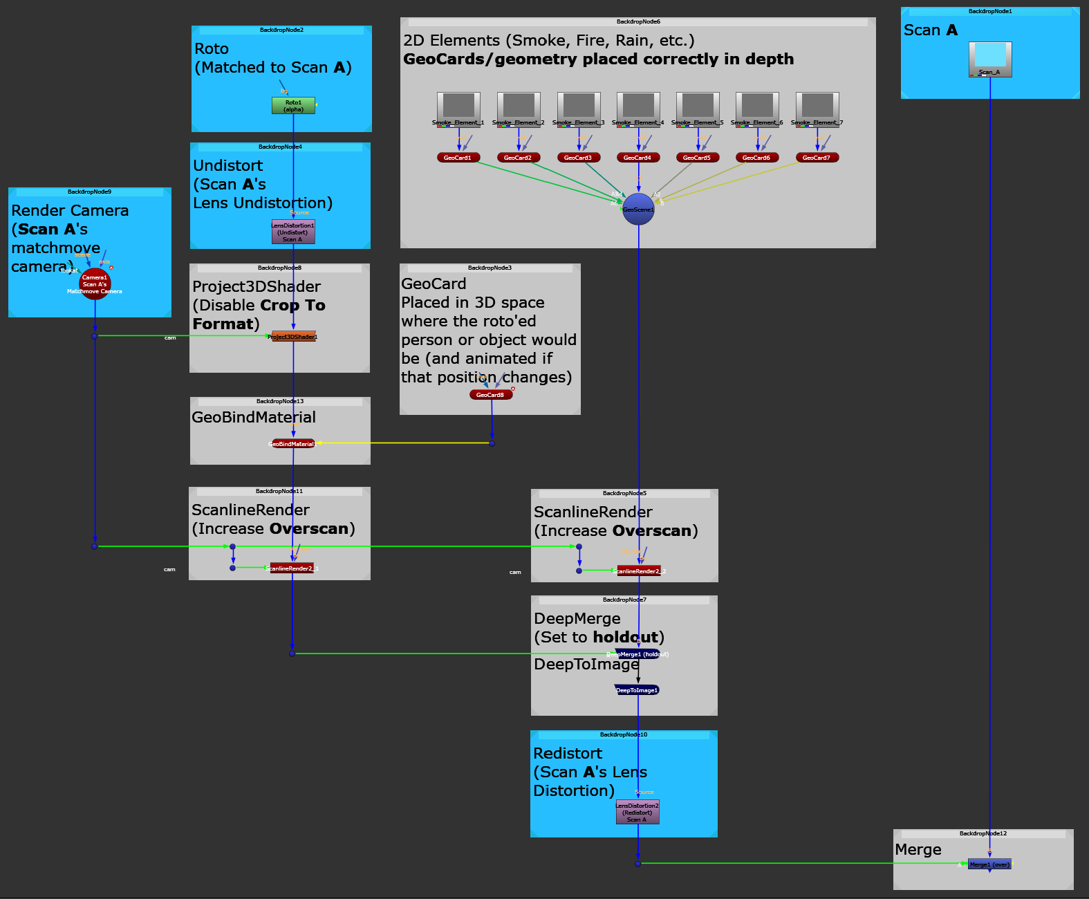
The projection setup for example use case 4.
On the left, the roto for the person in the scan (undistorted by the scan’s lens undistortion) is being live-projected on a Card/GeoCard (positioned in between the element Cards/GeoCards in 3D space – with its position animated to match the person’s change in position over the course of the shot), and output with a ScanlineRender node using the matchmove camera for the scan as the render camera. (The ScanlineRender node outputs Deep by default).
In the middle, you can find all the elements placed on Cards/GeoCards (positioned correctly in depth) at the top, which are also being output with a ScanlineRender node using the matchmove camera for the scan as the render camera.
Below that, the Deep output of the roto is holding out the Deep output of the elements, with a DeepMerge node with its operation set to holdout. The held out Deep output of the elements is then output to 2D using a DeepToImage node. Finally, lens distortion (from the scan) is applied to the result, before it’s all being merged over the scan on the right.
Example Use Case 5:
Adding movement and parallax to a still image, such as a matte painting.
Matte paintings will often be exported with layers for each part of the scene, for example the sky, the background, midground, and foreground buildings, the roads, and so on.
To get parallax between these layers with a moving camera, and make the matte painting feel three-dimensional, you can project the different layers of the matte painting onto Cards/GeoCards or other geometry positioned at different depths in the 3D scene:
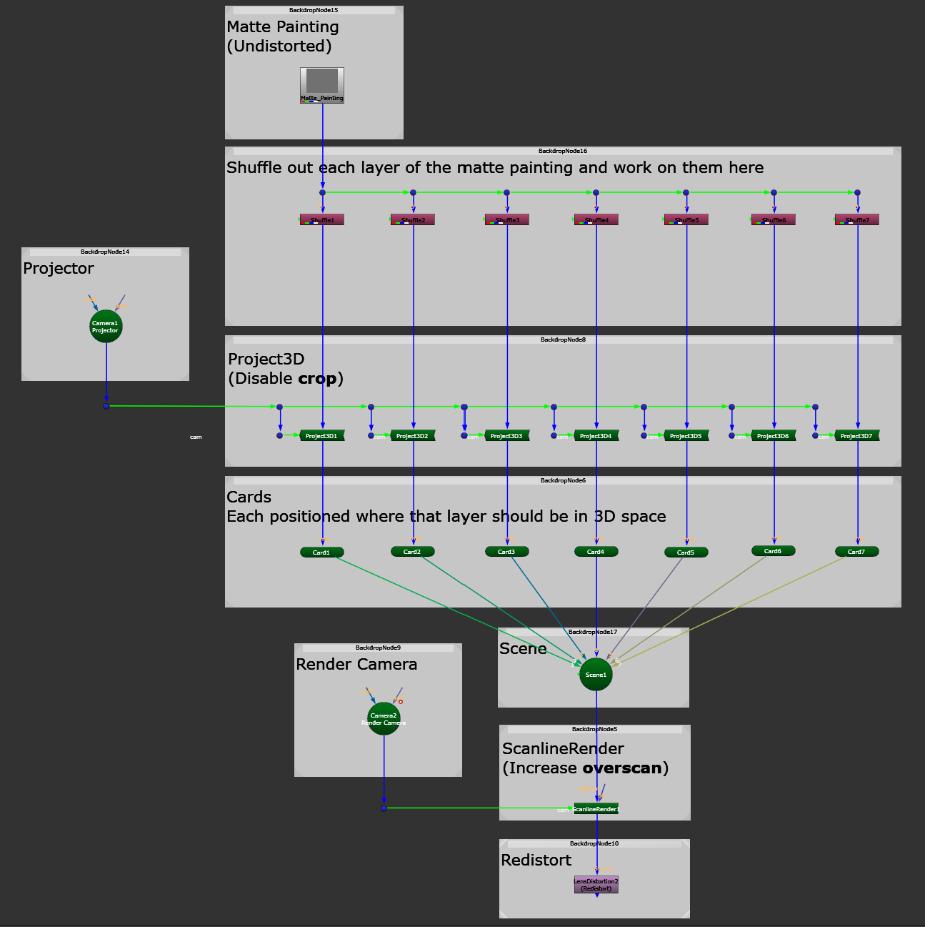
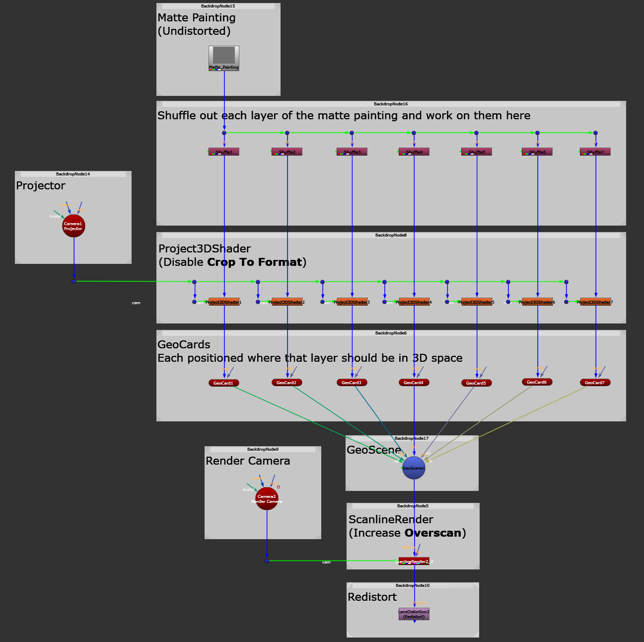
The projection setup for example use case 5.
If the matte painting is very large and has many layers – becoming heavy to work with – you can make separate projection setups for groups of layers, and then either Merge or DeepMerge the ScanlineRender nodes together.
This allows you to precomp each projection output, and save processing power. (If you’re just merging the ScanlineRender nodes together, the precomp can be rendered with a normal Write node, but if you want to deep merge them together, render the precomp with a DeepWrite node).
Example Use Case 6:
Changing or touching up textures and adding details to objects in CG renders.
This is very useful because you avoid having to go back and re-render the CG, and so you can save a lot of time and resources.
If the object that you want to adjust in your CG render is static, you can just use the general projection setup and project a patch over it. However, objects in a CG render will often be animated, and so you’ll need to make the projection stick to the surface instead of sliding off it, which it would do with the regular setup.
I’ve described how to do this in Sticking A Projection Onto Animated Geometry In Nuke. Here is the setup:
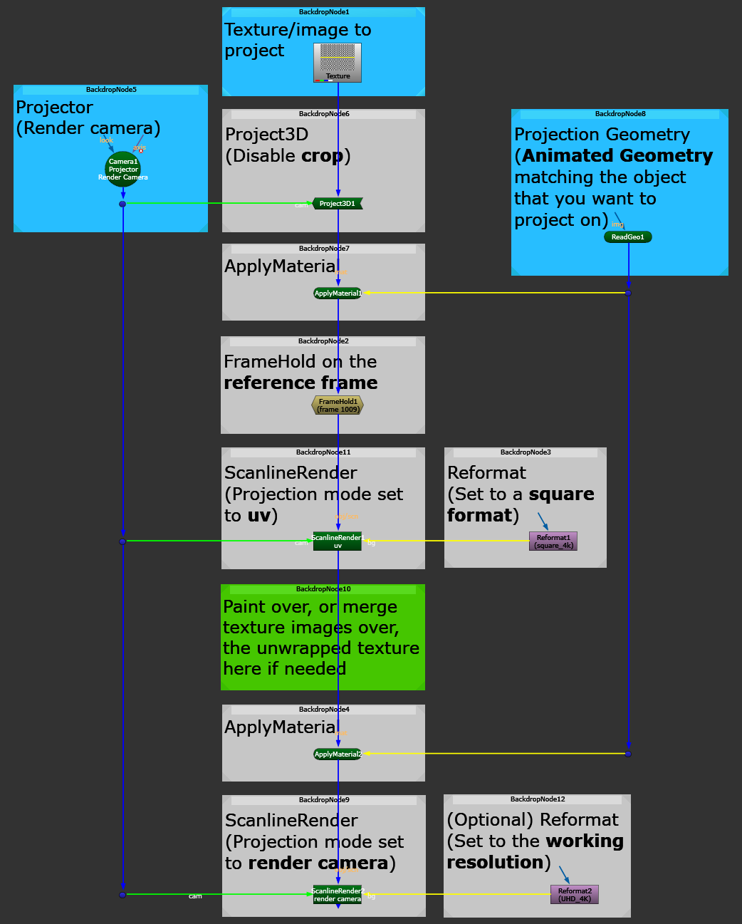
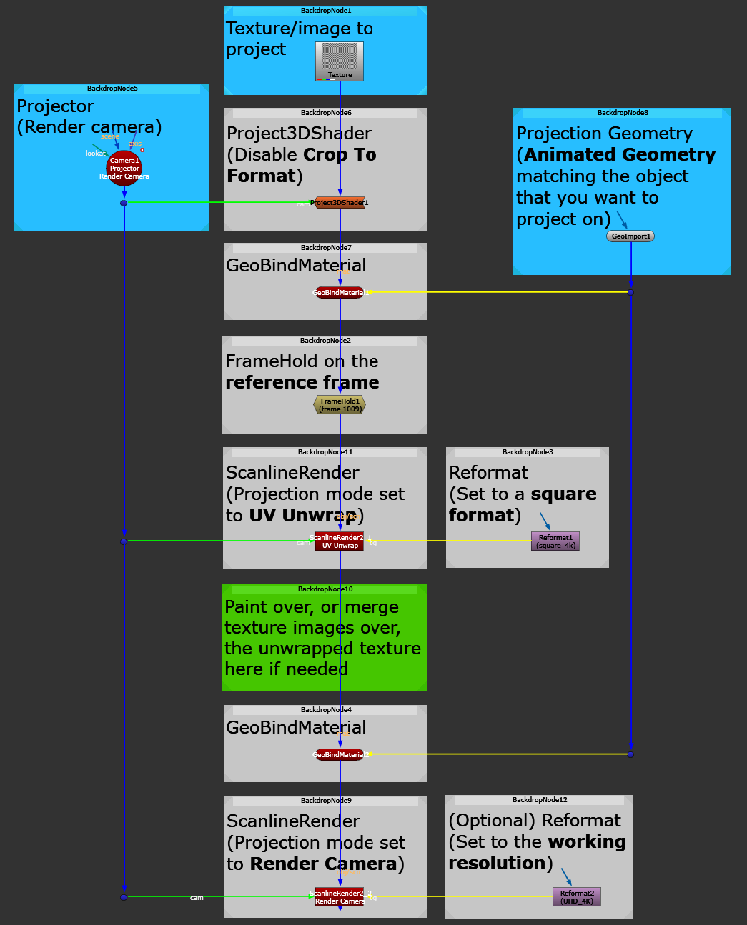
The projection setup for example use case 6.
This video shows some more practical examples of working in the UV space that we’ve set up:
Compositing in UV space with Projections | Nuke [Advanced]
With the new GeoProjectUV node and its Reference Frame setting, we can simplify the setup above and avoid having to render out an intermediate UV space:
Nuke 17.0 | Sticky Projections
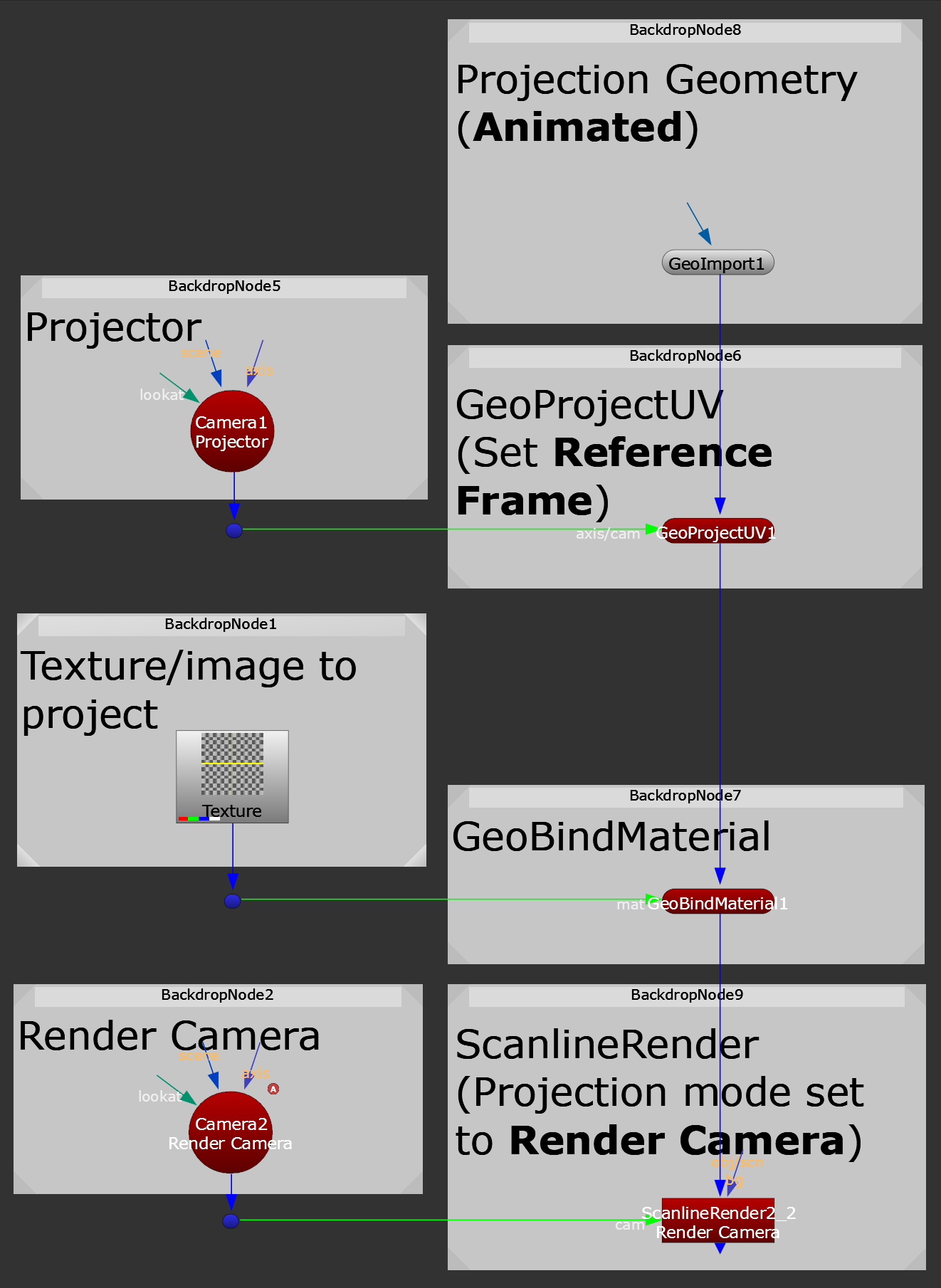
A simplified projection setup for example use case 6.
Example Use Case 7:
Stabilising a shot.
You can use the matchmove camera for your shot to stabilise the camera move in your scan.
This is useful if the camera in the scan is a bit jittery or bumpy, and you want it to be more stable or locked off. And, since you have the matchmove camera already, the track is ‘free’. I.e. it saves you from having to set up any (potentially complicated) 2D tracking and stabilisation in comp.
To do this, we’ll once again make use of live-projection:
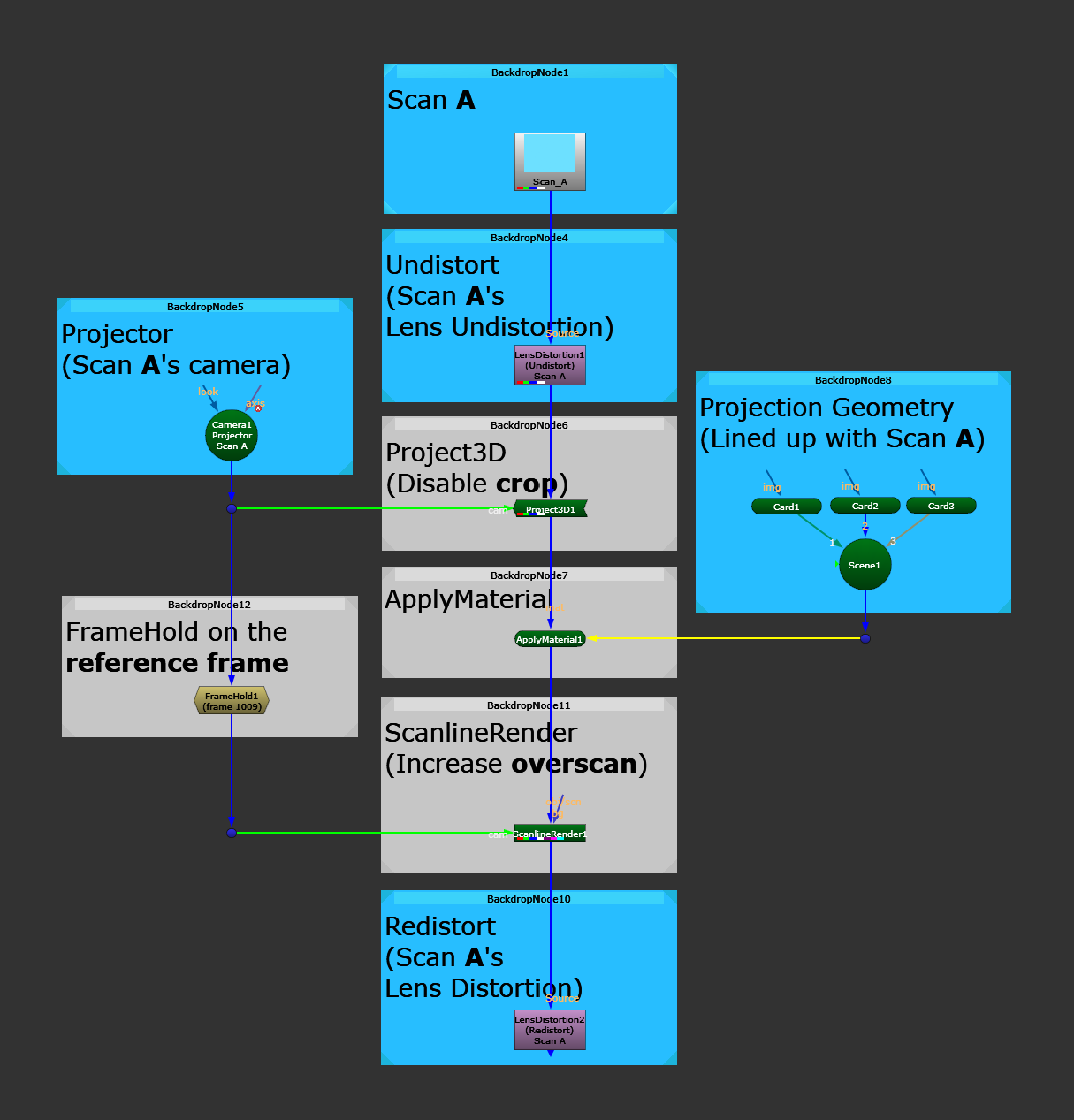
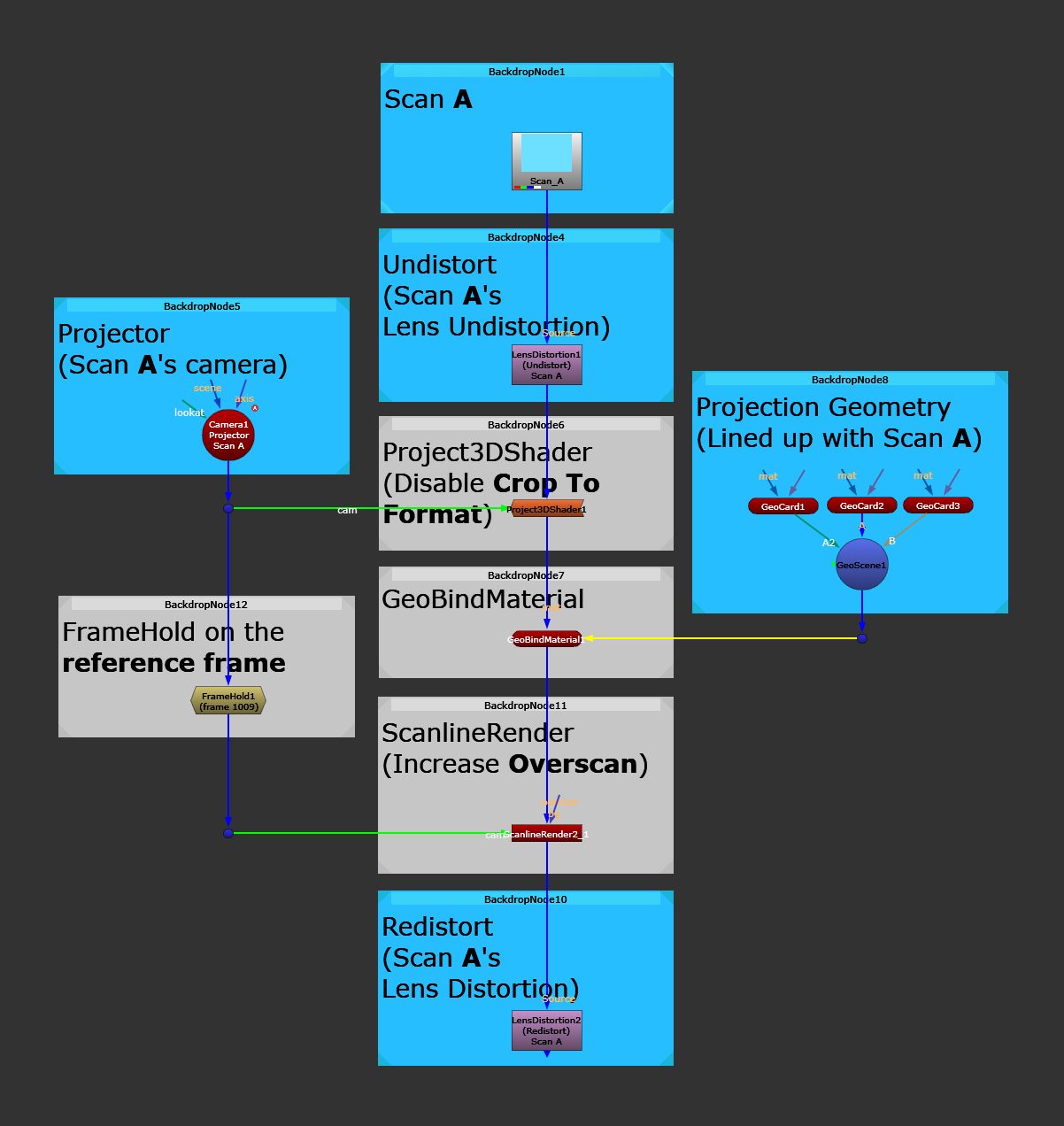
The projection setup for example use case 7.
The setup above will output a stabilised scan, with a locked off camera (the viewpoint of the camera on the reference frame).
If you instead would like to keep some of, or most of, the camera move, but only remove the bumps or jittering, you can make a copy of the matchmove camera and connect the ScanlineRender to the new camera instead of to the FrameHold node.
Then, scale and/or filter the animation curves in the new camera to remove some of the camera move or the bumps/jitter:
Select the new camera and go to the Curve Editor.
Then, select the animation curve that you want to reduce (for example the translation in X).
Select all the points on the curve, and then drag the top of the selection box down to scale the curve down, and reduce the extent of the curve.
Or, if you want to smooth out the curve, select all of the points (or the points in a particularly bumpy section of the curve), then right-click → Edit → Filter. Choose the number of times to filter in the pop-up window and hit OK to smooth the curve.
Now, the setup will stabilise the scan, and then re-photograph the stabilised footage with less camera move/bumpiness/jitter, depending on what you did.
Next, is a useful tip: even if you don’t intend to stabilise the scan for the final output, having a stabilised scan is great for doing other tasks more efficiently, for example rotoscoping.
– You could stabilise the scan using the setup pictured above, minus the redistortion, and view the stabilised output of the ScanlineRender when rotoscoping.
Then, when you’re happy with the roto, project it using the reverse projection (i.e. matchmove) to restore the camera move again:
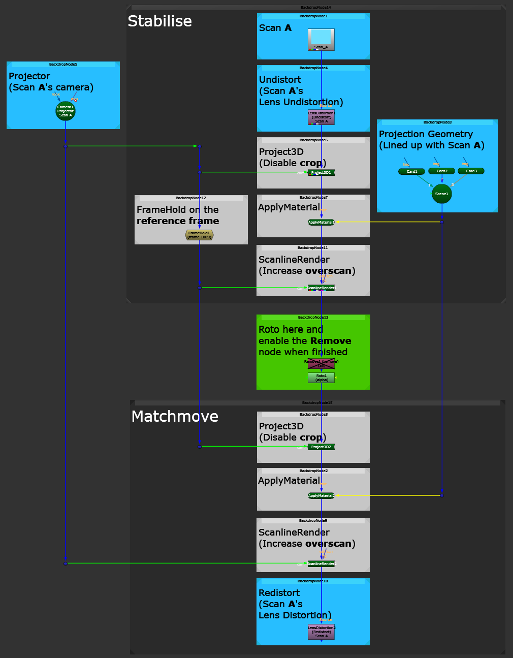
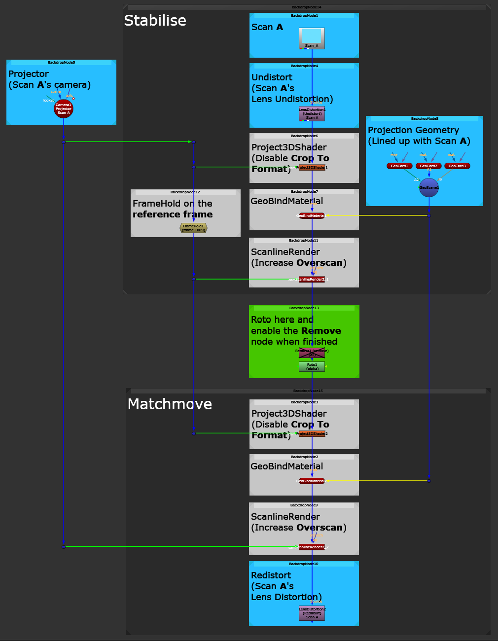
Setup for stabilising the plate for doing roto work, then projecting the roto to restore the camera move to it.
This will output just the reprojected roto matching to the original scan, which you can then use further in your comp.
And that concludes this guide on camera projections in Nuke. But there is more to explore:
Further Watching
If you want to dive deeper into advanced projections, here are some great videos from Trixter:
Advanced Projection (Part 01)
Advanced Projection (Part 02)
I hope you found this tutorial useful. For more Nuke tips & tricks, see Nuke.