Creating Astigmatic Lens Effects In Nuke
⭐ How to add tangential and sagittal astigmatism to an image…
⭐ How to add tangential and sagittal astigmatism to an image…
⭐ Companions: Please sign in to access the bonus gizmo at the end of the guide 😊
There is a Companions exclusive Nuke gizmo at the end of this guide.
Radial And Concentric Streaks
If you’ve studied the imperfections that camera lenses leave in a captured image, or have simply worked in VFX long enough, you may have noticed that most of the distortions and aberrations in the image happen away from the centre, near the corners and edges of the frame.
You’ll already be familiar with many of these aberrations – and you may have tools/gizmos for recreating them in Nuke – like chromatic aberration or vignetting.
However, some types of aberrations are a bit more exotic and complex in their nature, like for instance astigmatism.
There are two kinds of astigmatism: tangential astigmatism and sagittal astigmatism. Let’s see how they affect an image using a grid of point light sources and a checkerboard as examples:
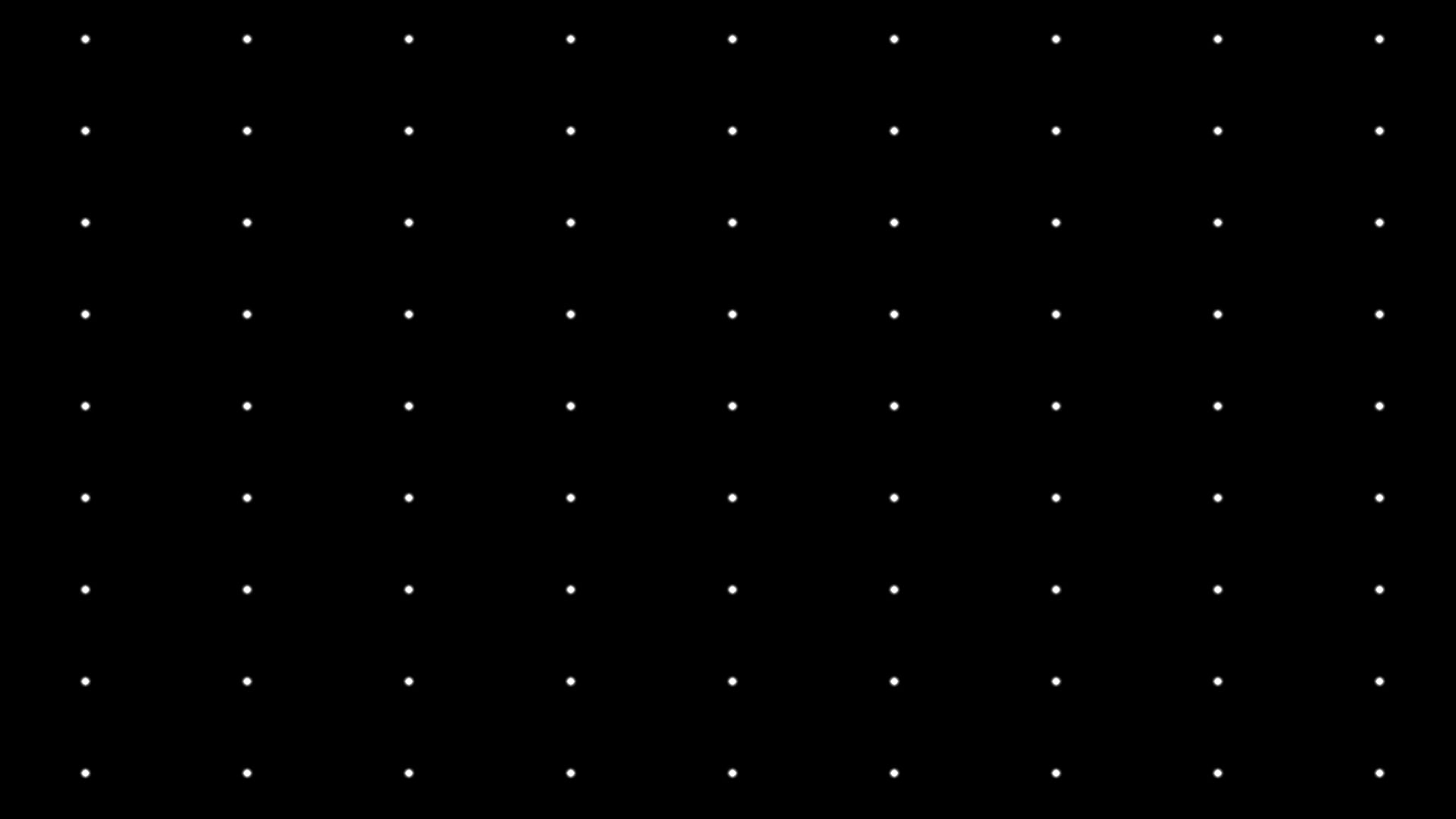
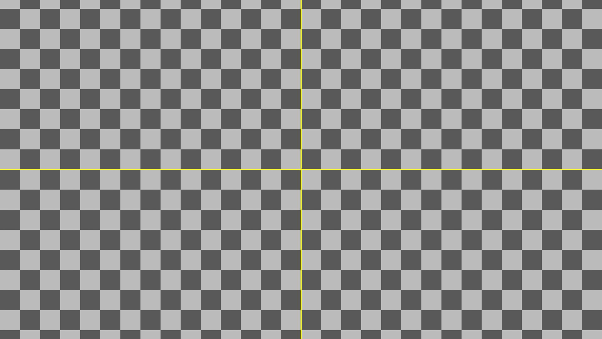
A grid of point light sources (left) and a checkerboard (right) with no astigmatism.
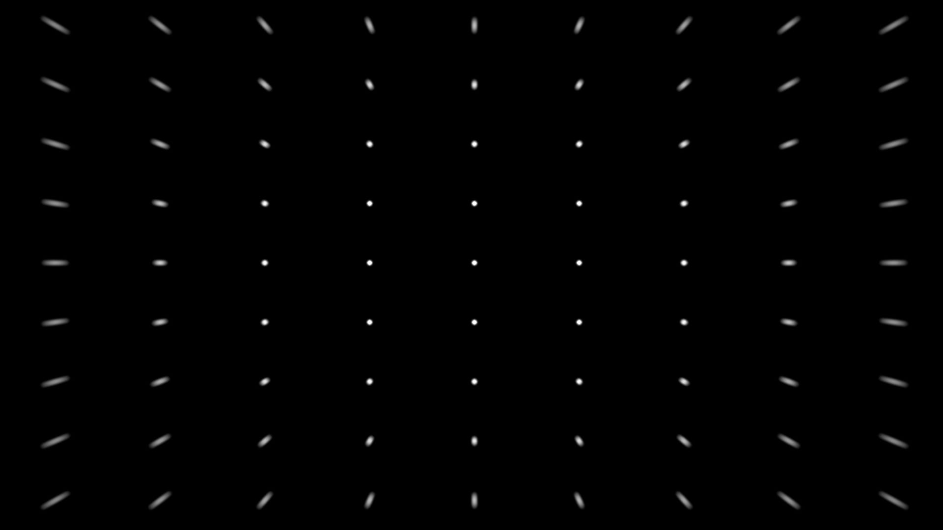
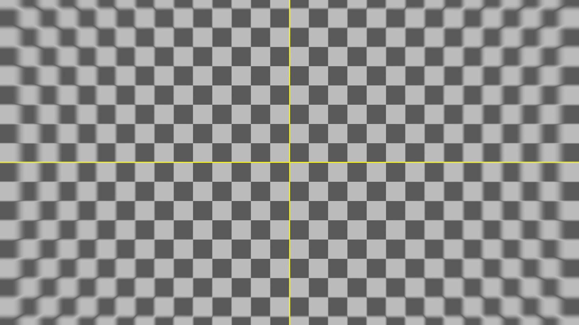
Tangential astigmatism spreads the point light sources (left) and the checkerboard pattern (right) in lines that seem to radiate from the centre of the image.
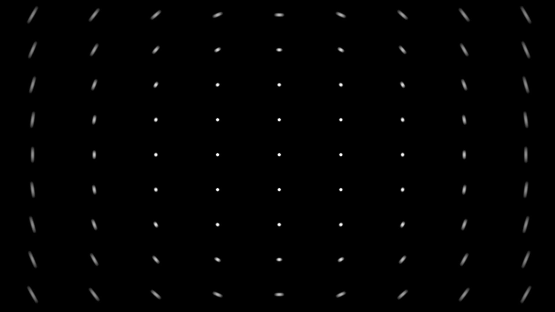
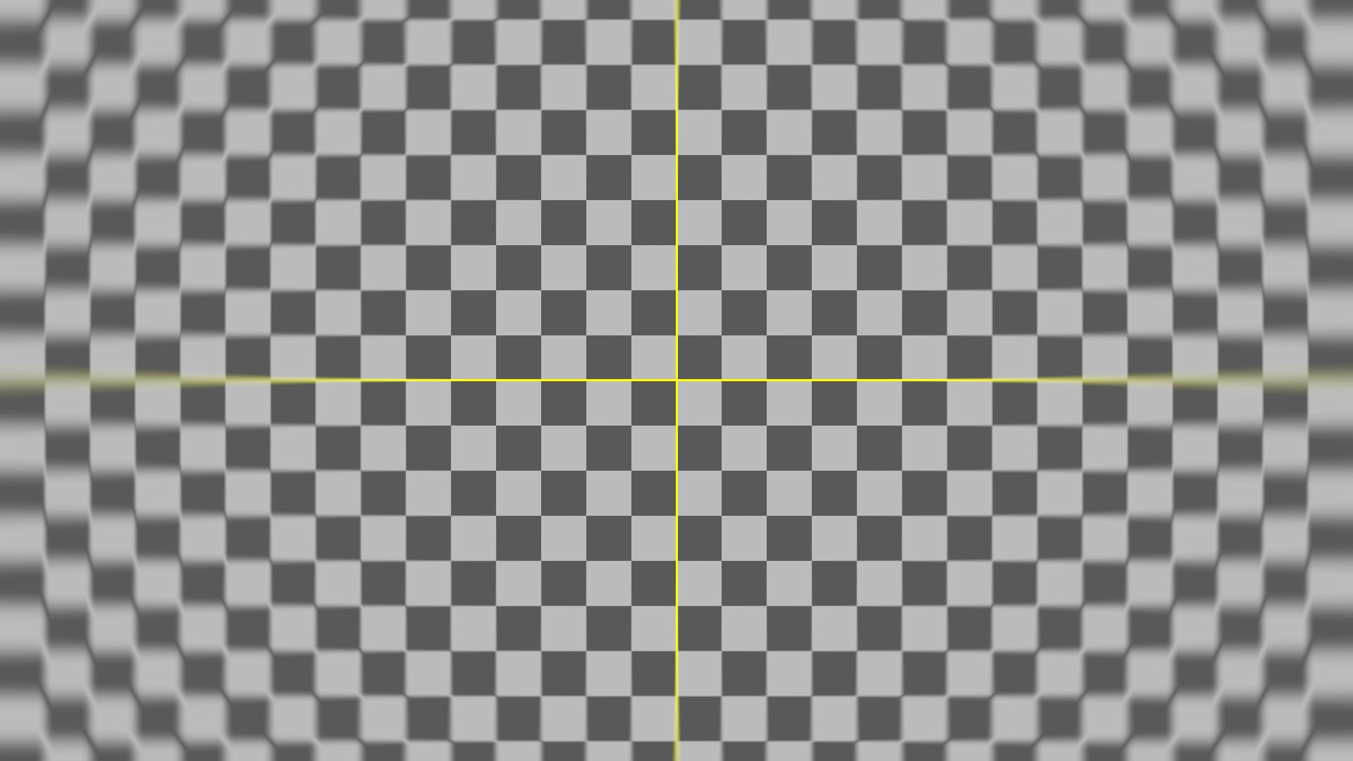
Sagittal astigmatism spreads the point light sources (left) and the checkerboard pattern (right) as if rotated about the centre of the image.
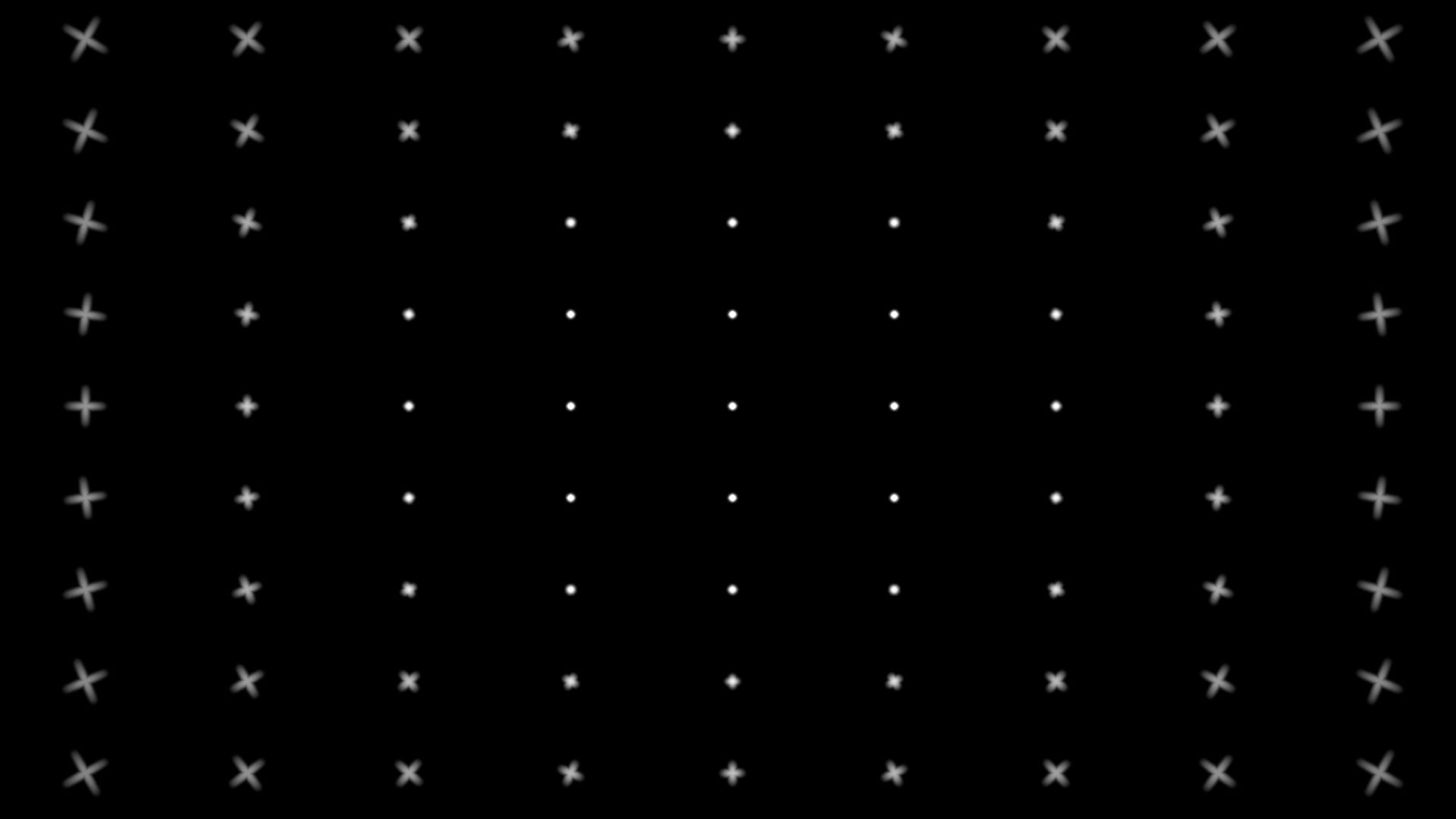
If we superimpose both of the earlier images of the point light sources with astigmatism – combining the tangential and sagittal astigmatism – we can see that the lines form crosses in which each line is at a 90 degree angle to the other.
Astigmatism happens when a light ray which is passing through a lens gets focused at two different points (or, for many rays, on two different surfaces) depending on which plane the light is propagating in:
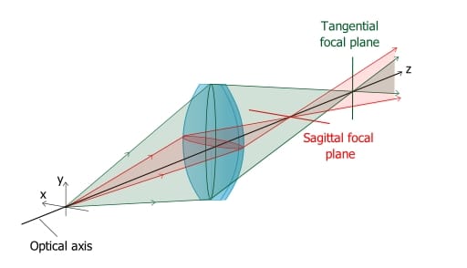
Astigmatism diagram. (Source).
Depending on where the sensor sits relative to the two focal surfaces, the blur can look elongated in one direction or the other, and we get either tangential or sagittal astigmatism.
Let’s create the effect in Nuke.
Tangential Astigmatism
Okay, so we need to smear the pixels that are around the edges and corners of the frame outward, away from the centre of the image.
And, the effect should increase in strength the further away from the centre the pixels are located.
We can do that using a VectorBlur node and some custom vectors.
The VectorBlur node blurs each pixel into a straight line using vectors to determine the direction of the blur.
A positive x-component of the vector will result in the pixel being blurred to the right, and a negative x-component will make it blur to the left.
A positive y-component of the vector will result in the pixel being blurred upwards in the frame, and a negative y-component will make it blur downwards.
A value of 0 in either vector component means no blurring in that respective direction.
And so, for our custom vectors, we want the centre pixel to have a value of 0. And then, going clockwise around the frame, we want the following:
- The top left corner pixel should have a maximum negative value in x and a maximum positive value in y. I.e. that pixel will be blurred diagonally up and to the left, the most.
- The top right corner pixel should have a maximum positive value in x and a maximum positive value in y. I.e. that pixel will be blurred diagonally up and to the right, the most.
- The bottom right corner pixel should have a maximum positive value in x and a maximum negative value in y. I.e. that pixel will be blurred diagonally down and to the right, the most.
- The bottom left corner pixel should have a maximum negative value in x and a maximum negative value in y. I.e. that pixel will be blurred diagonally down and to the left, the most.
The values of the pixels in between the centre pixel and the corner pixels should gradually increase/decrease toward the corner pixels.
This might sound like a tall order, but we can create these custom vectors quite easily by adjusting a standard ST map.
First let’s make an ST map using an Expression node:
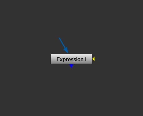
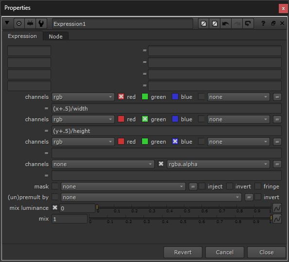
Creating a standard ST map using an Expression node.
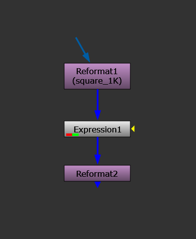
Before we continue, let’s connect a Reformat node into the input of the Expression node, and set it to a square format. This will be important for modifying the vectors later.
A 1K square format is usually fine, but you can always increase it later, if needed.
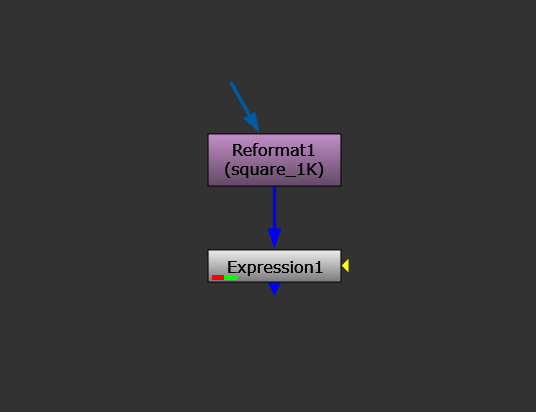
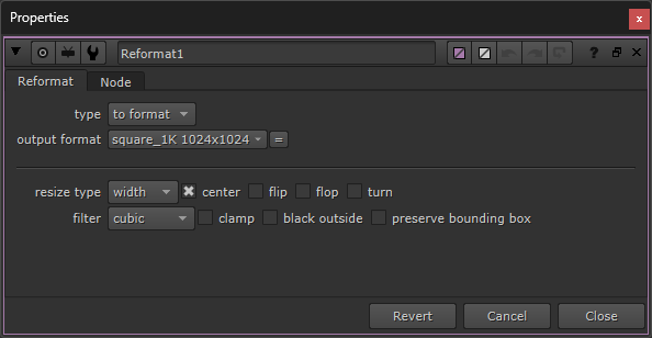
Adding a Reformat node with a square format to the input of the Expression node.
– Which gives us this image:
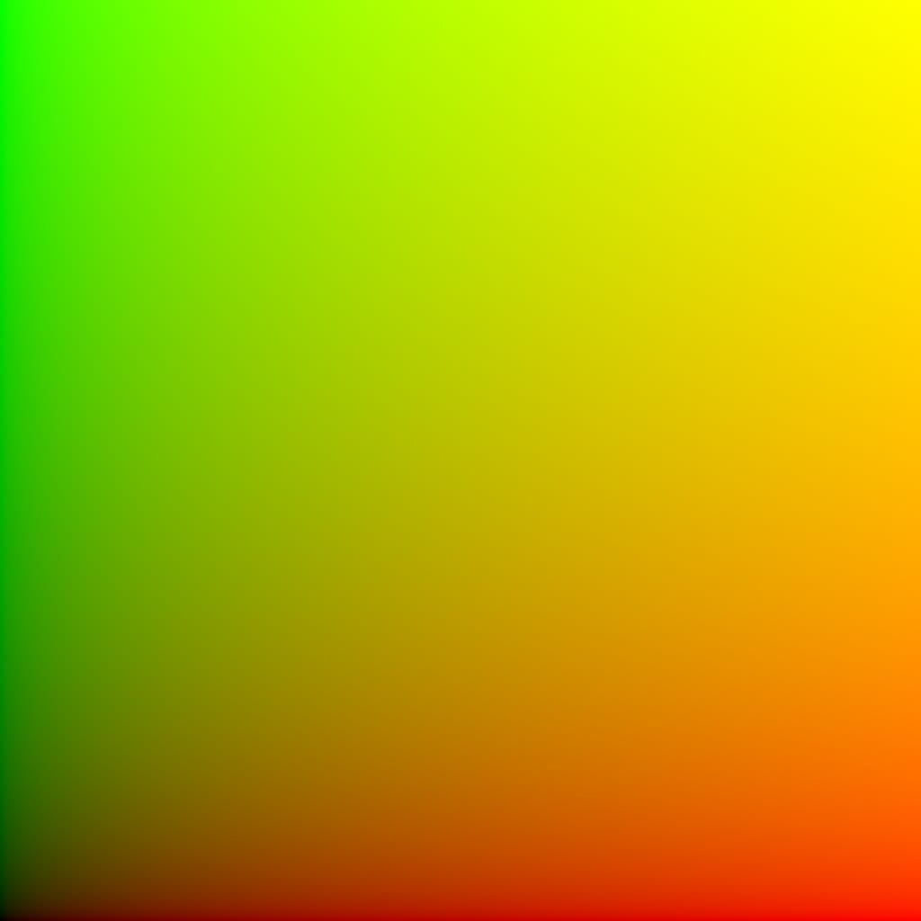
A standard, square, ST map.
Next, let’s modify the ST map by changing our expression.
Currently, the ST map’s pixel values range from a value of 0 in both x and y in the bottom left corner, to a value of 1 in both x and y in the top right corner.
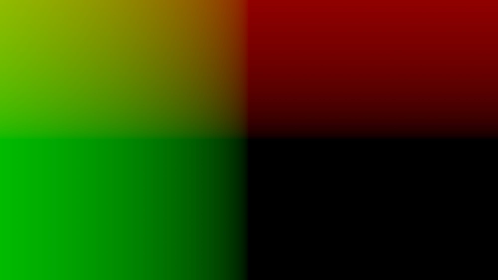
By subtracting 0.5 from all the pixel values, we shift them all over to exactly how we need them, and the range of values now goes from -0.5 (now the maximum negative value of the ST map) to 0.5 (now the maximum positive value of the ST map):
- The centre pixel (which used to be 0.5 in x and y) becomes 0 in x and y.
- The top left corner pixel (which used to be 0 in x and 1 in y) gets a value of -0.5 in x and 0.5 in y. (I.e. a maximum negative value in x and a maximum positive value in y).
- The top right corner pixel (which used to be 1 in x and 1 in y) gets a value of 0.5 in x and 0.5 in y. (I.e. a maximum positive value in x and a maximum positive value in y).
- The bottom right corner pixel (which used to be 1 in x and 0 in y) gets a value of 0.5 in x and -0.5 in y. (I.e. a maximum positive value in x and a maximum negative value in y).
- The bottom left corner pixel (which used to be 0 in x and 0 in y) gets a value of -0.5 in x and -0.5 in y. (I.e. a maximum negative value in x and a maximum negative value in y).
And all the pixel values in between gradually increase/decrease from the centre pixel and out to the corner pixels.
Exactly what we want.
The modified expression becomes:
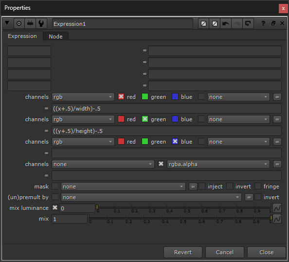
The modified Expression node.
– Which gives us this image:
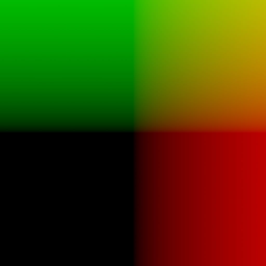
The modified ST map. (Although the whole bottom left corner appears just black, i.e. you might mistakenly think it all has a value of 0, only the centre pixel in the image has a value of 0 in x and y. The other pixels go into negative values – Nuke just displays them as black).
Next, let’s reformat this ST map to our project format (for this example, I’m using a 4K UHD format) so that we can use it:
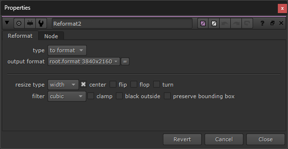
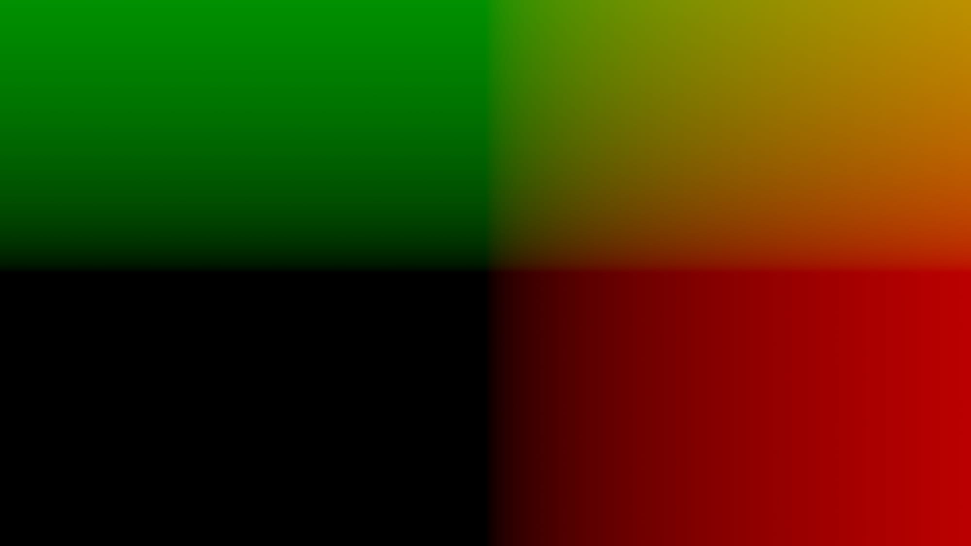
Reformatting the ST map into our project format.
Let’s copy these vectors into a layer which the VectorBlur node can use for the blurring.
You can call your custom layer anything – I’ll create a layer called astigmatismVectors with the channels u and v:
Using a Copy node, copy the red channel from the ST map into astigmatismVectors.u and the green channel into astigmatismVectors.v.
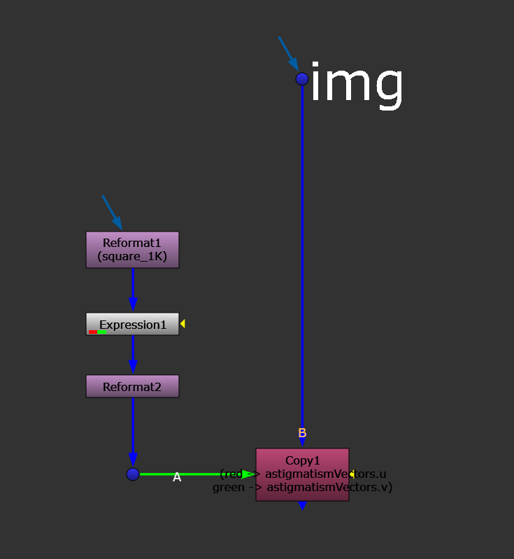
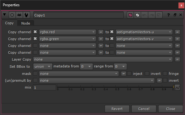
Copying the vectors into a custom layer.
Next, create a VectorBlur node with these settings:
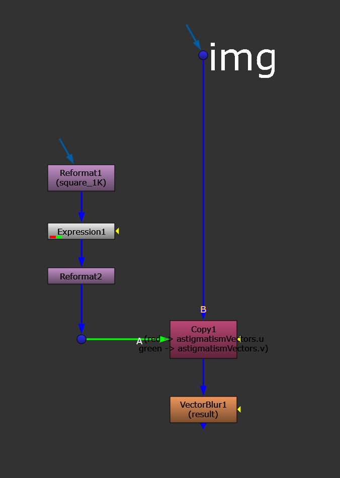
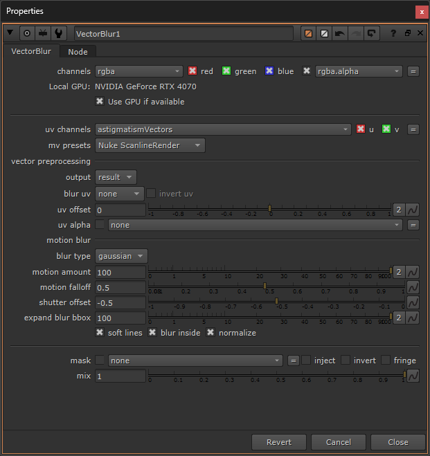
Creating the VectorBlur node.
The motion amount represents the strength of the effect. The motion falloff controls the falloff of the blur. Setting the shutter offset to -0.5 ensures that the blurring happens with its centre at the pixel, meaning the pixels will smear into a line with the original pixel position as the centre of the line. Turning on soft lines helps soften any harsh edges in the effect.
Connect the setup to your image and now we have a working tangential astigmatism effect.
However, if you look closely, the centre of your image is being affected (except for the pixel in the dead centre of the frame). We only really want the corners and edges of the frame to be affected, while keeping most of the centre of the frame intact.
To fix this, we can change the values of the vectors near the centre of the image closer to 0. We can do that using a Radial mask and a stencil operation:
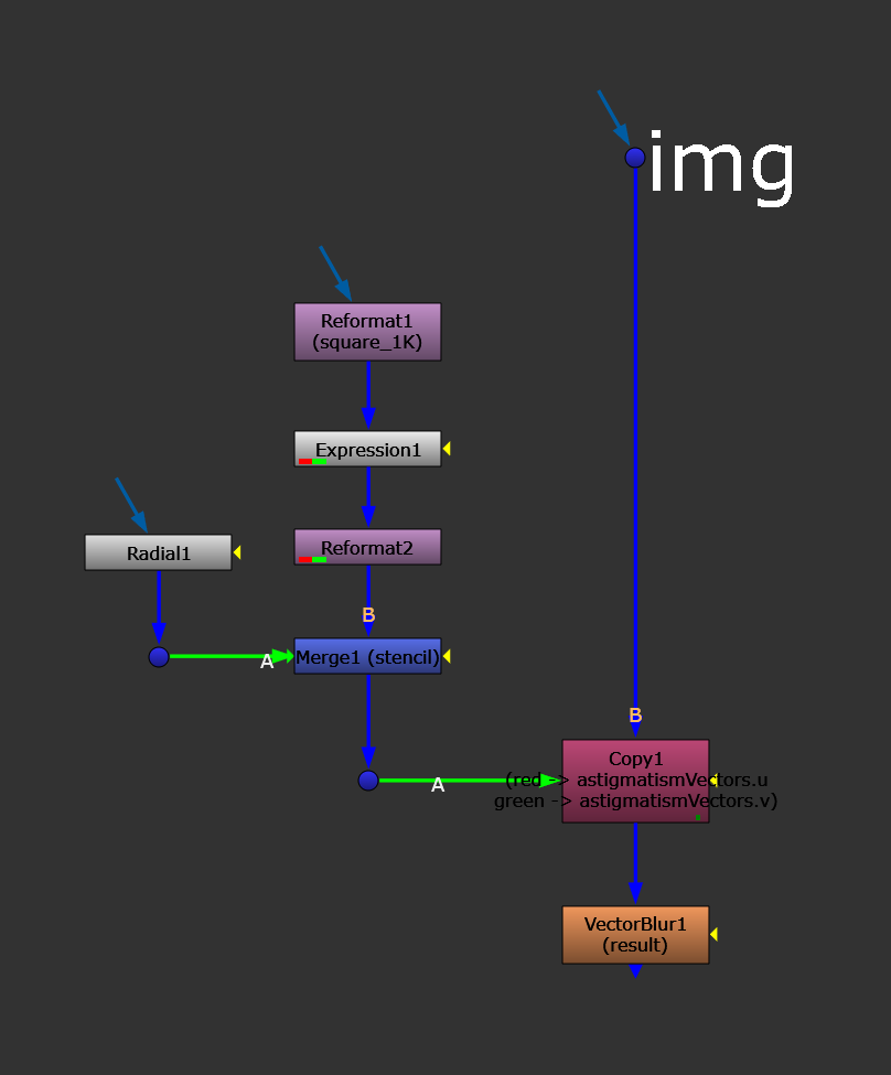
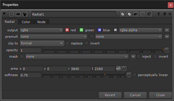
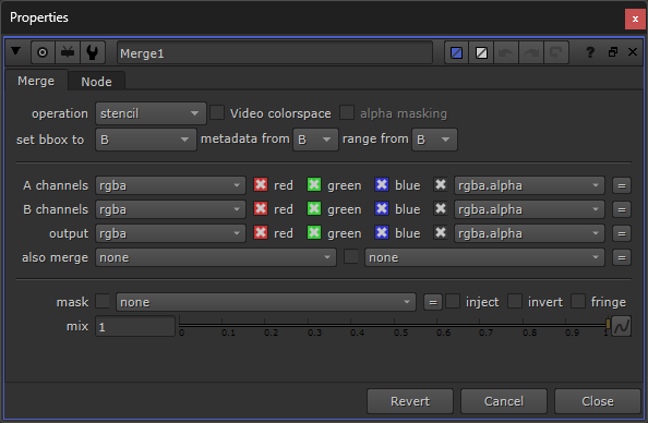
Changing the values of the vectors near the centre of the frame closer to 0.
Above, I set the Radial node’s area to the project format, and lowered the softness a little bit to reduce the distortion more near the centre of the frame.
Here, with the radial mask, you’ll likely need to make some adjustments to match the astigmatism in your scan. Move the Radial node’s area (i.e. the grey box in the Viewer) around and adjust the softness until the effect is appearing in the right part of the frame with the right falloff.
You can scale, blur, and grade the radial mask, as well, and adjust the motion amount in the VectorBlur node until you get a perfect match.
Finally, if the centre of the frame is still being affected too much by the effect, you can also branch off a new pipe from the radial mask and crunch its black levels, and then Keymix back the original image (A) over your output (B) to restore even more of the centre of the frame.
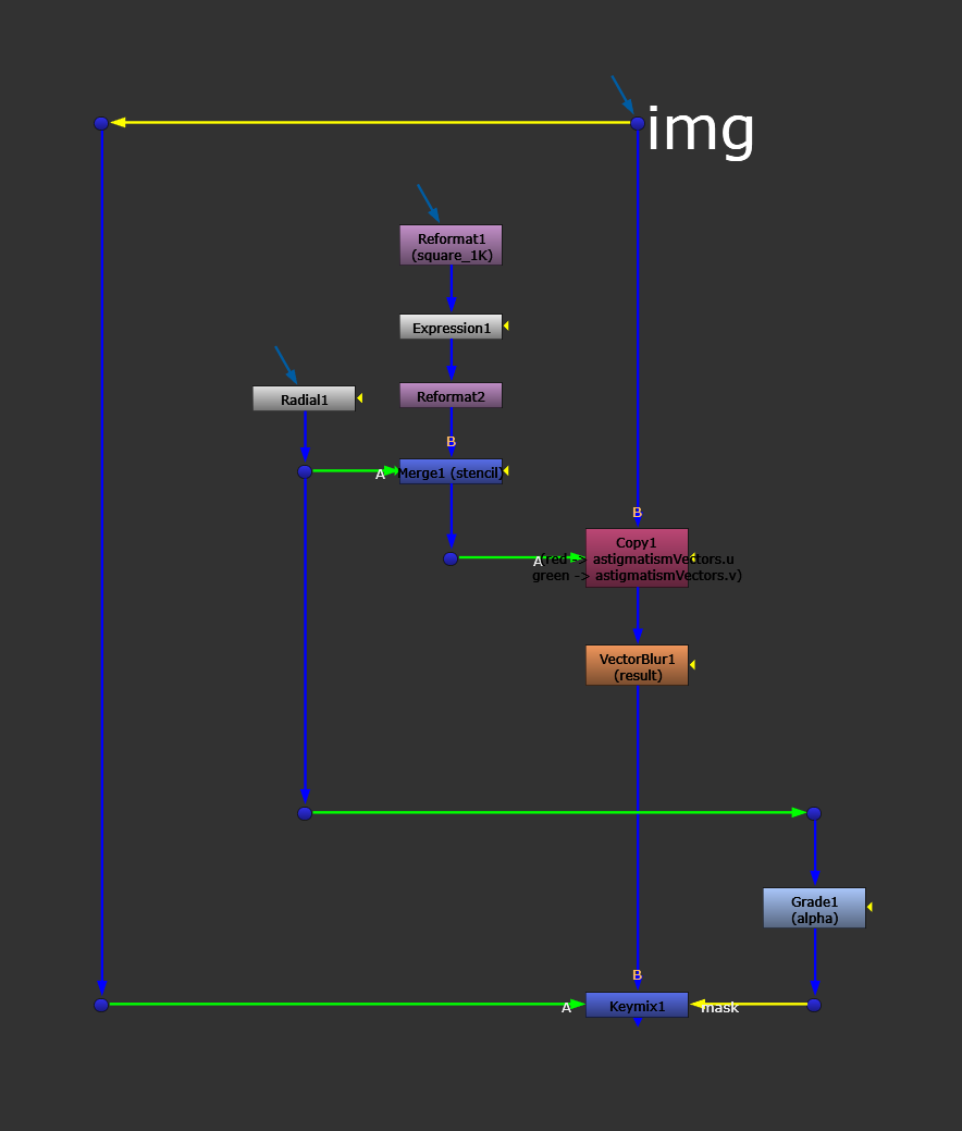
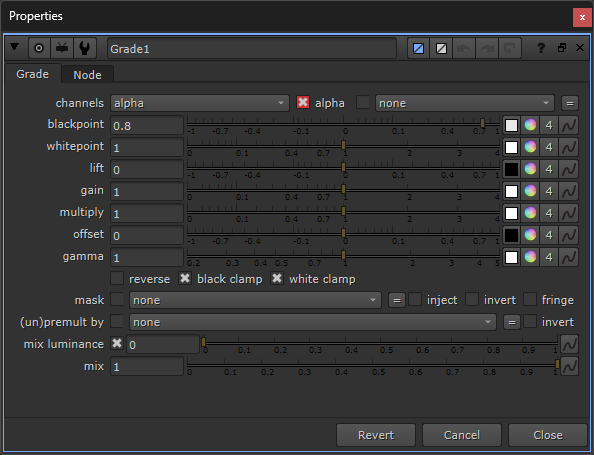
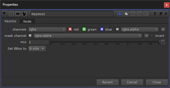
Keymixing back the original plate in the centre of the frame.
That’s the very basics of the setup, and will get you a working tangential astigmatism effect.
Sagittal Astigmatism
As mentioned earlier, the sagittal astigmatism is perpendicular to the tangential astigmatism.
And so, to create sagittal astigmatism, we can use the same setup as before but simply rotate the vectors by 90 degrees so that they’re pointing across the other way.
We can do that with a second Expression node, placed after the first one:
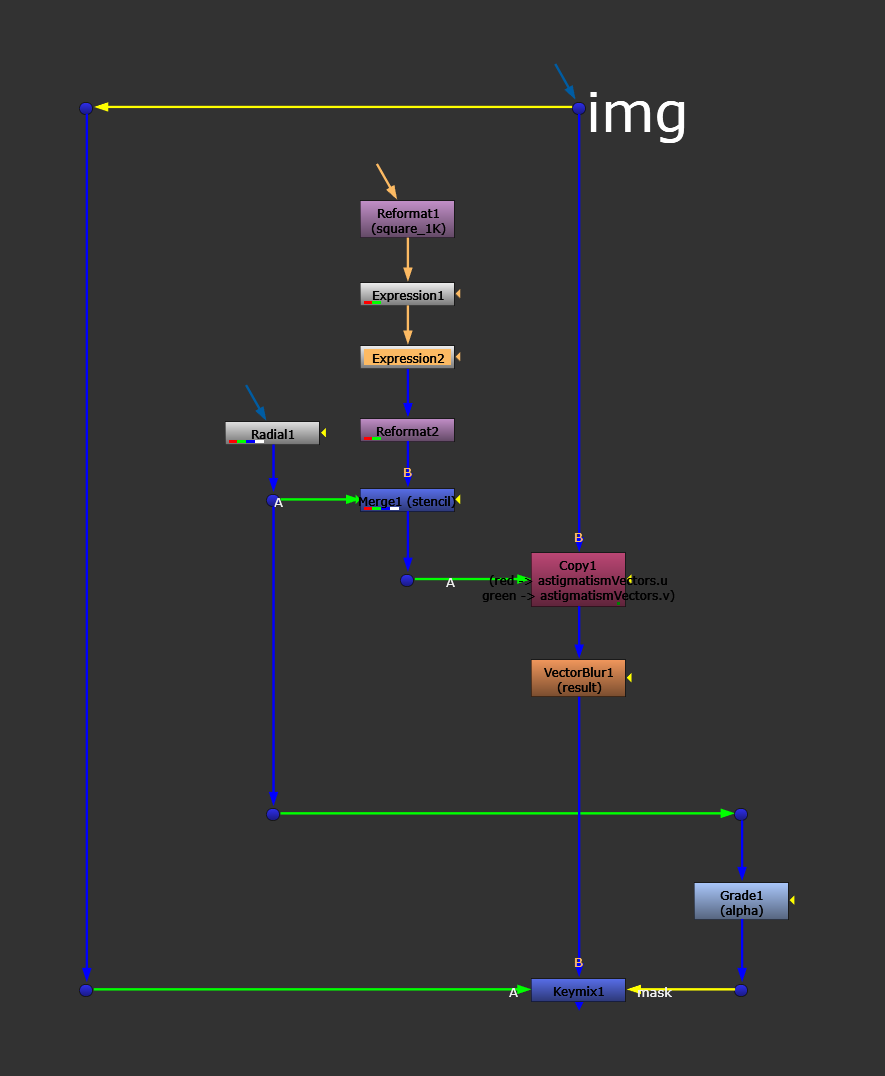
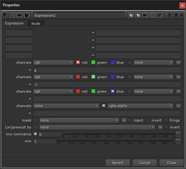
Adding a second Expression node to rotate the vectors 90 degrees, modifying our custom ST map.
This is why it was important to set the ST map to a square format earlier – to rotate the vectors correctly. With an image format that is wider than it is tall, or vice versa, the resulting vector rotation would not make the sagittal astigmatism exactly perpendicular to the tangential one.
And now we also have a working sagittal astigmatism effect. Enable and disable the second Expression node to swap between the two types of astigmatism.
That’s it for this guide, I hope you found it useful. 😊