Creating Iridescence In Nuke
How to emulate iridescence using hue remapping on a modified facing ratio pass…
How to emulate iridescence using hue remapping on a modified facing ratio pass…
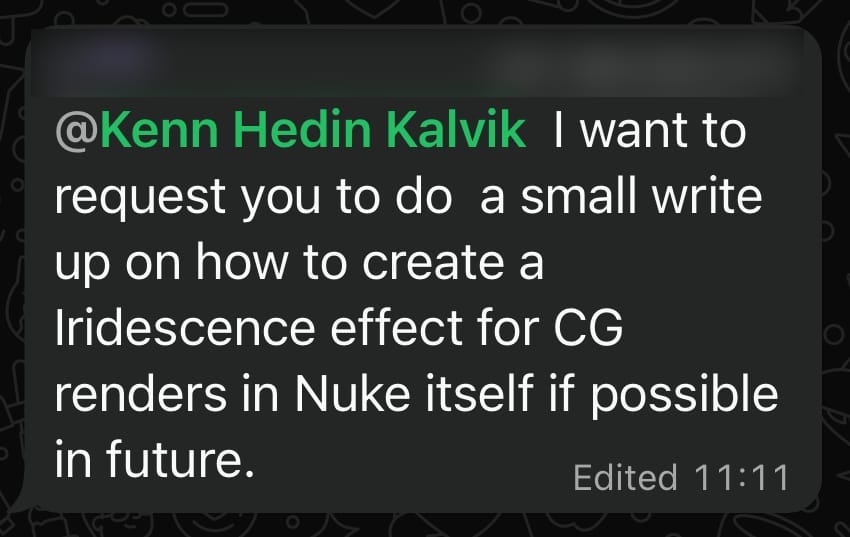
The topic of this tutorial was suggested by a Companion:
Iridescence
Iridescence is an optical phenomenon where the surface of an object appears to gradually change colour (hue) as the angle of observation or the angle of illumination changes.
It’s a shimmering, rainbow-like effect caused either by the interference of light waves within multilayered microstructures on the object’s surface or within thin films (such as oil), or by the dispersion of light through a diffraction grating.
We humans produce a wide range of objects which have iridescent effects, for example soap bubbles, pearlescent car paint, diffraction gratings for multispectral LIDAR systems, oil spills, or jewellery:
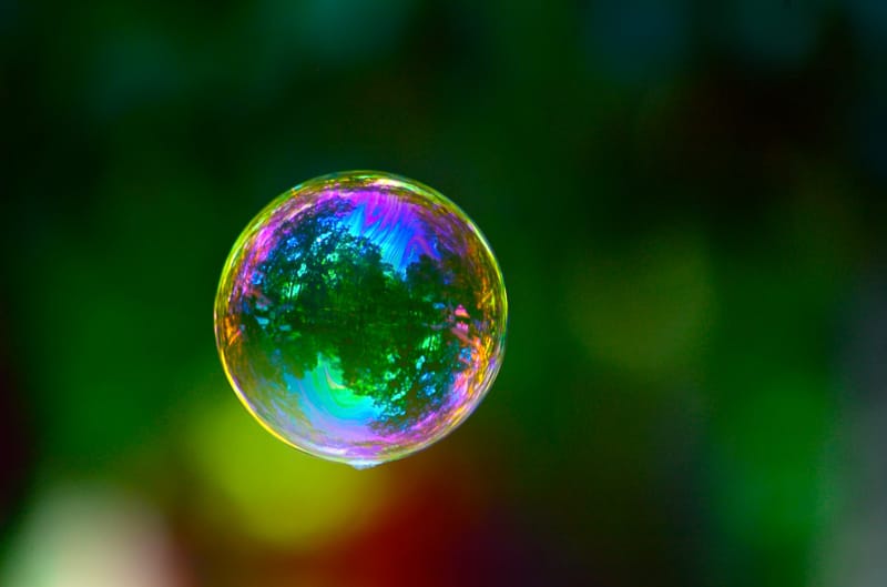
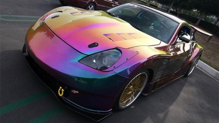
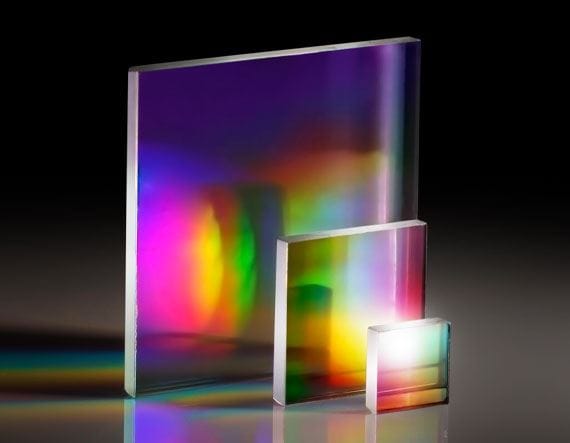
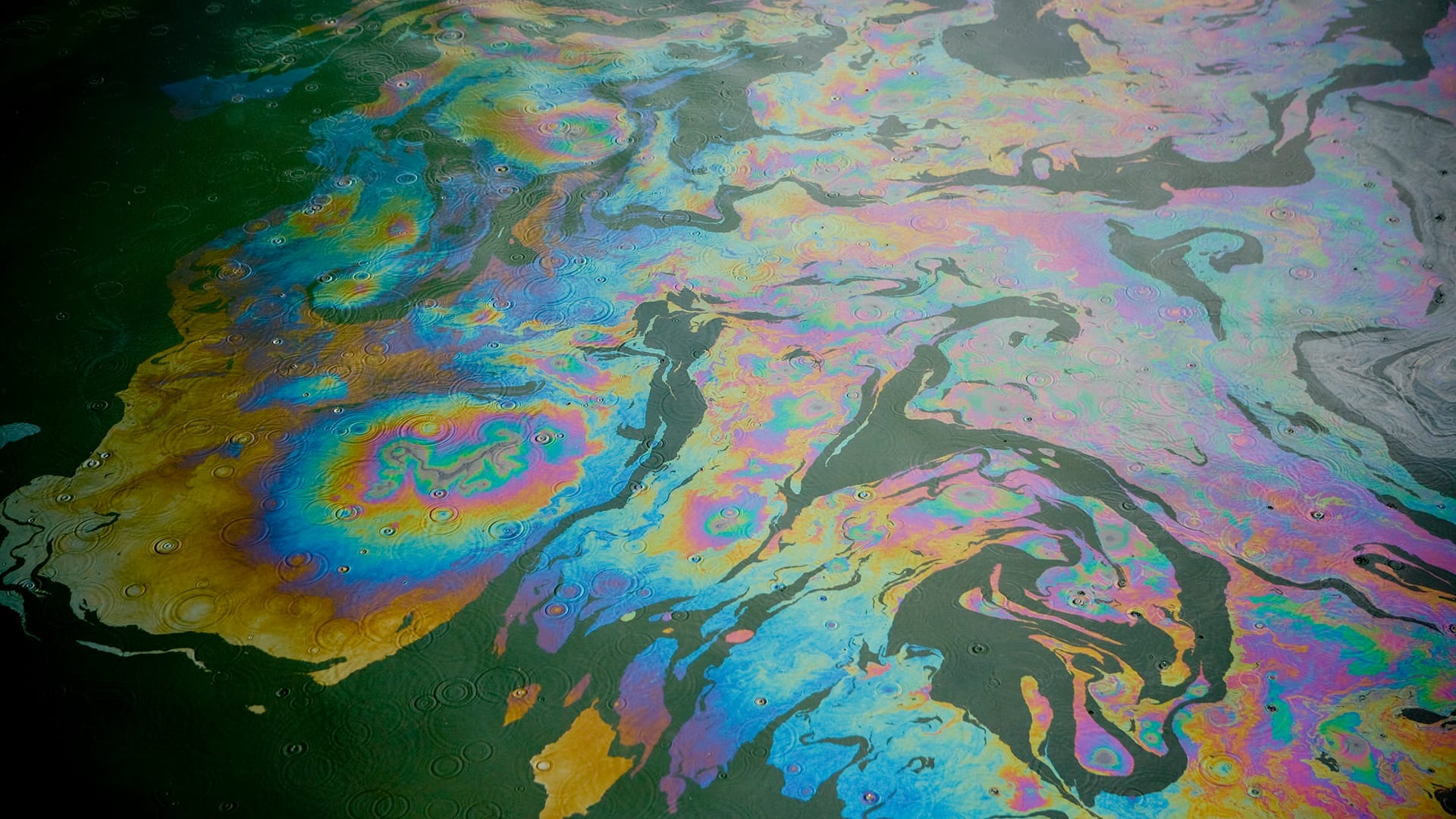

Examples of man-made/-assisted iridescence: (1) Soap bubble. (2) Pearlescent car paint. (3) Diffraction gratings. (4) Oil spill. (5) Jewellery.
Not only that, iridescence also appears in nature.
Take for instance the exoskeletons (i.e. shells) of several types of beetles:
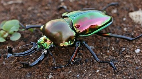
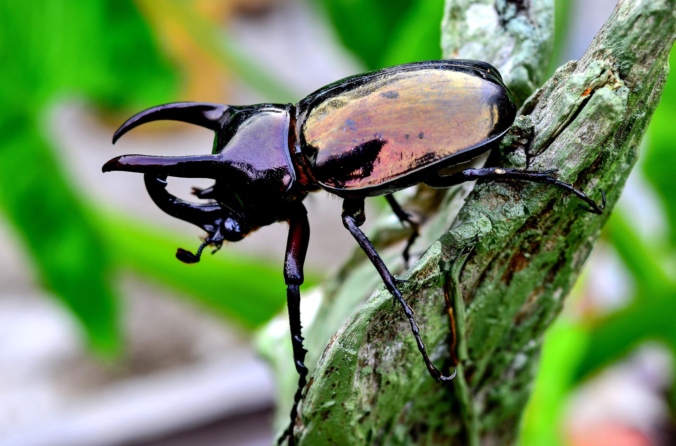
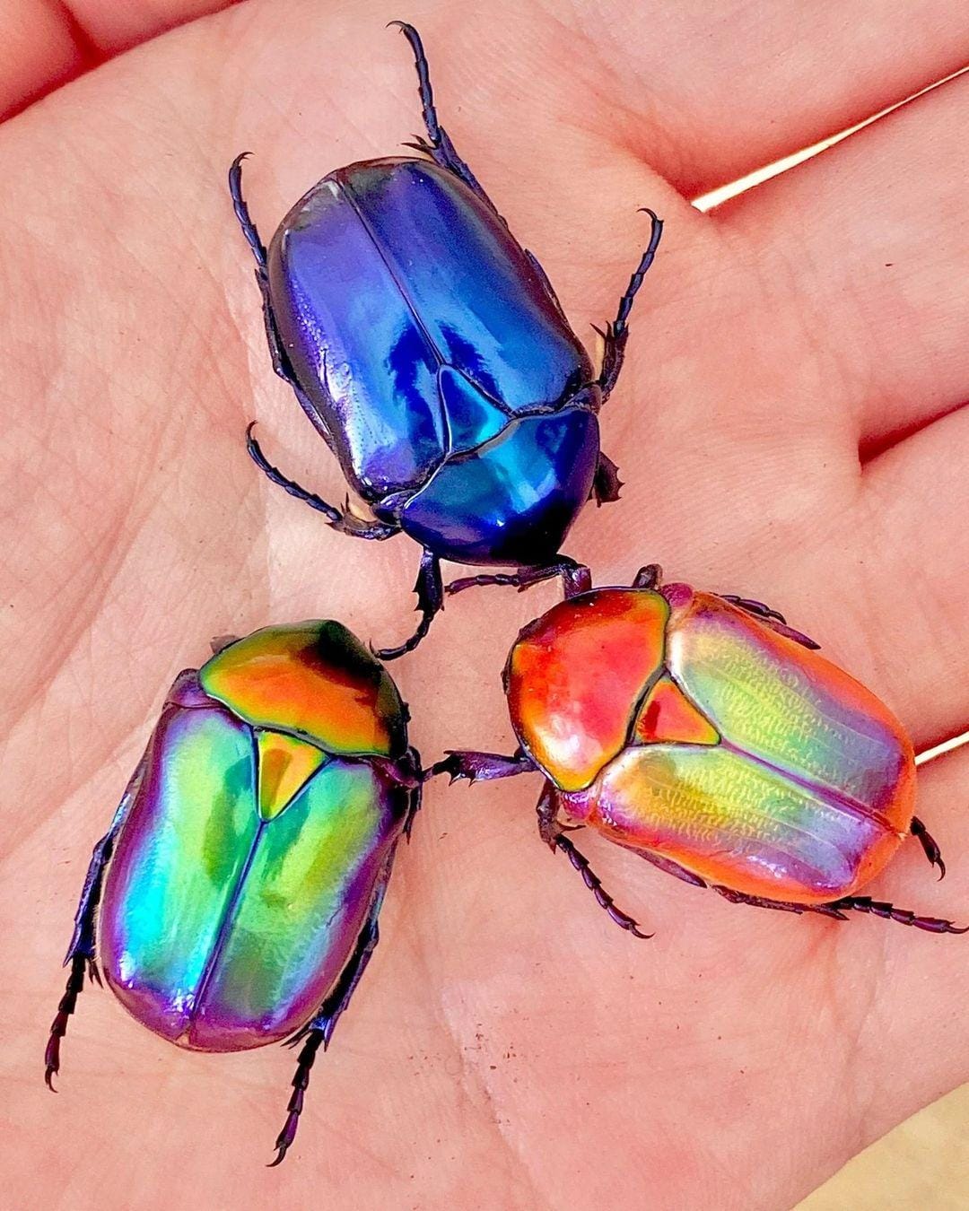
(1) Rainbow stag beetle. (2) Atlas beetle. (3) Jewel flower beetles.
Scientists have found that the shells of such beetles contain microstructures with alternating material compositions, which selectively reflect light of certain colours, causing iridescence.
We can also see iridescence appearing in other insects such as butterflies, in clouds, in fish, and in birds, leaves, crystals, shells, and many other types of flora and fauna:
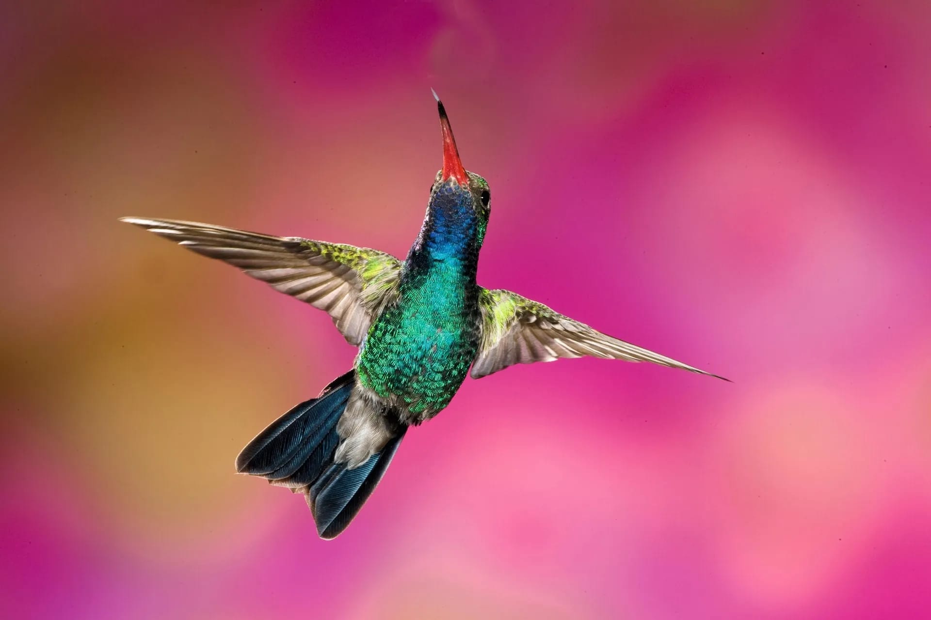
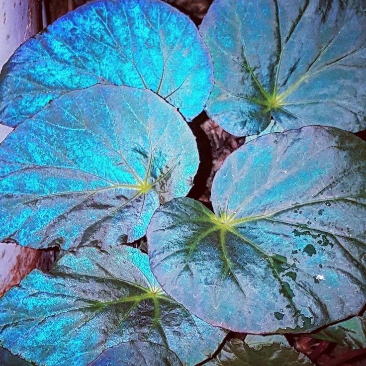
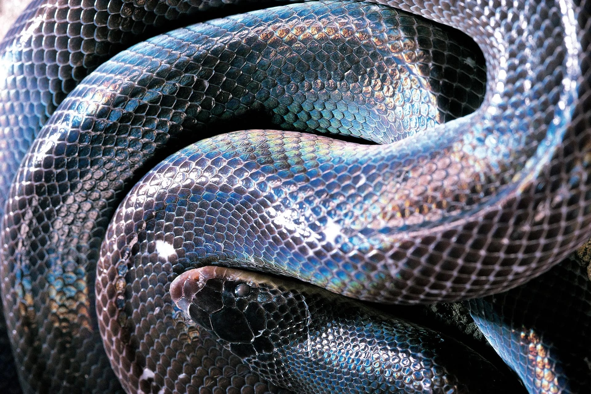
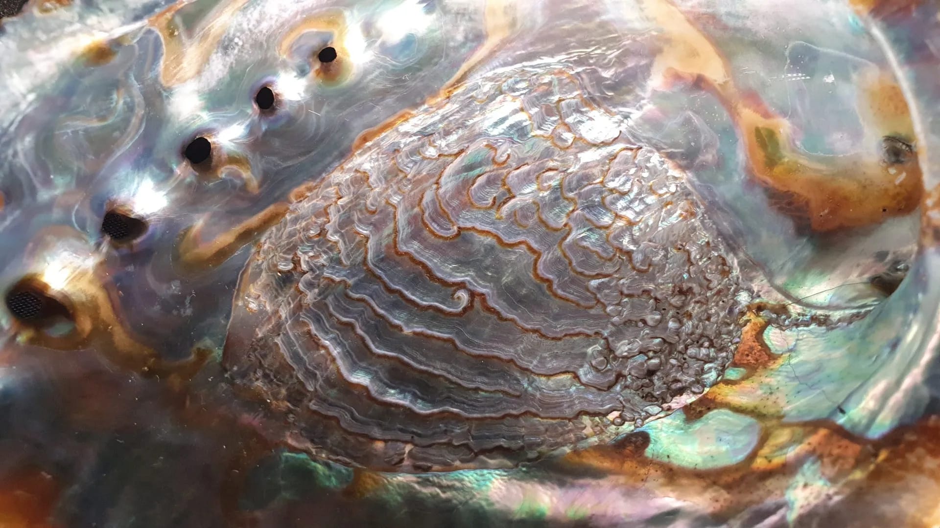
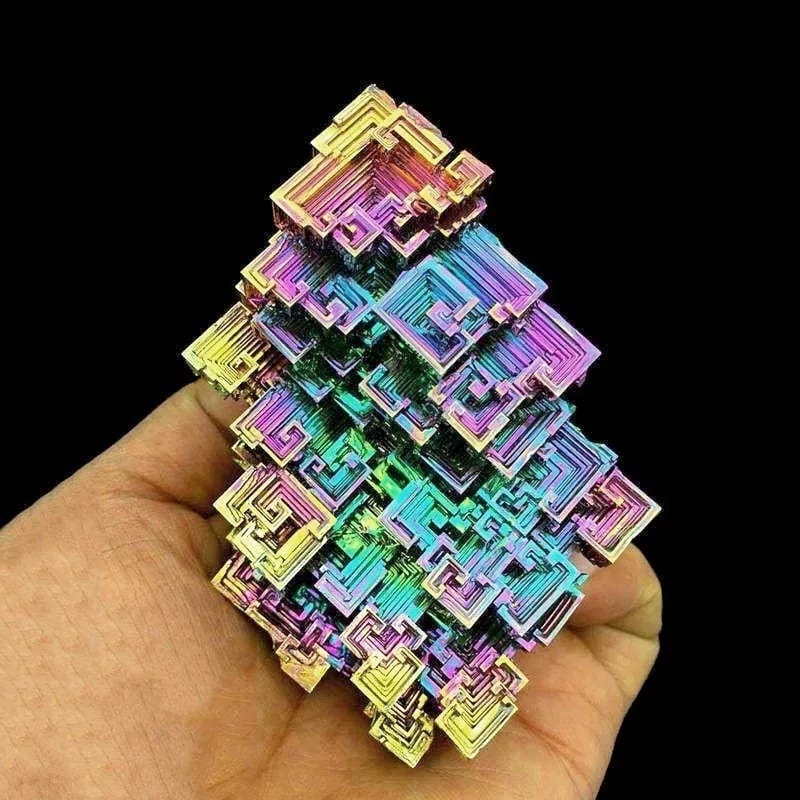
Examples of natural iridescence: (1) Broadbilled hummingbird. (2) Begonia Pavonina. (3) Mexican burrowing python. (4) Mother of Pearl. (5) Bismuth crystal.
And so, you may encounter projects where you'll have to emulate an iridescent effect.
Before we dive into how to build the effect in Nuke, let’s break it all down:
- Iridescence alters the hue of the surface of an object. We still see specular highlights and reflections along with occlusion and shadows in the presence of iridescence – iridescence mixes in with these effects.
- The range of colours of natural iridescent objects can be narrow, for example shifting between two or three colours as the viewing angle changes. I.e. we may not see the whole rainbow of colours in the iridescence.
- In the case of diffraction, the entire rainbow of colours will typically be observed as the viewing angle changes.
- Iridescence is highly dependent on the viewing angle, i.e. the angle between the surface of the object and the camera. Different colours will typically show on surfaces facing the camera vs. surfaces that are at a glancing angle.
- It’s also highly dependent on the angle of illumination, i.e. the angle between the surface of the object and the source(s) of light. Different colours will typically show on surfaces depending on where the lights are in the scene.
- In real life, there is no such thing as perfect conditions. Surfaces won’t be perfectly uniform, and films won’t have the same thickness throughout – there will be imperfections. And so, there will be variations in the iridescent colours. For example, surfaces facing the same direction (i.e. they share the same viewing and illumination angle) may not always share the same iridescent colour.
Keep these things in mind, and let’s move into Nuke.
Creating The Effect In Nuke
To create the effect in Nuke, we’ll make heavy use of the lookdev techniques developed by Julius Ihle back in 2015.
His approach still stands the test of time, but hopefully I’ll be able to shed some more light on it, and add useful things to it.
Already, we have some variables to consider when creating the effect:
- The range of colours to display where the iridescence appears.
- The dynamic viewing/illumination angles, which should be reflected in a control matte.
- Imperfections causing variations in the iridescence, which should also be reflected in the control matte.
Colour Gradient
Like Julius described, Nuke represents hue in a 0-1 range, and values above 1 and below 0 repeat the hue pattern.
We can visualise this using a Colorspace node, and converting an image with a 0-1 ramp in the red channel, and a value of 1 in the green and blue channels, from the HSV colour space to Linear RGB.
HSV stands for Hue, Saturation, and Value. In this colour space:
- Hue is represented by the red channel.
- Saturation is represented by the green channel.
- And, Value (brightness) is represented by the blue channel.
So, converting an image with a 0-1 ramp in the red channel, and a value of 1 in the green and blue channels from the HSV colour space to Linear RGB will create a colour gradient with the entire spectrum of fully saturated colours, like this:
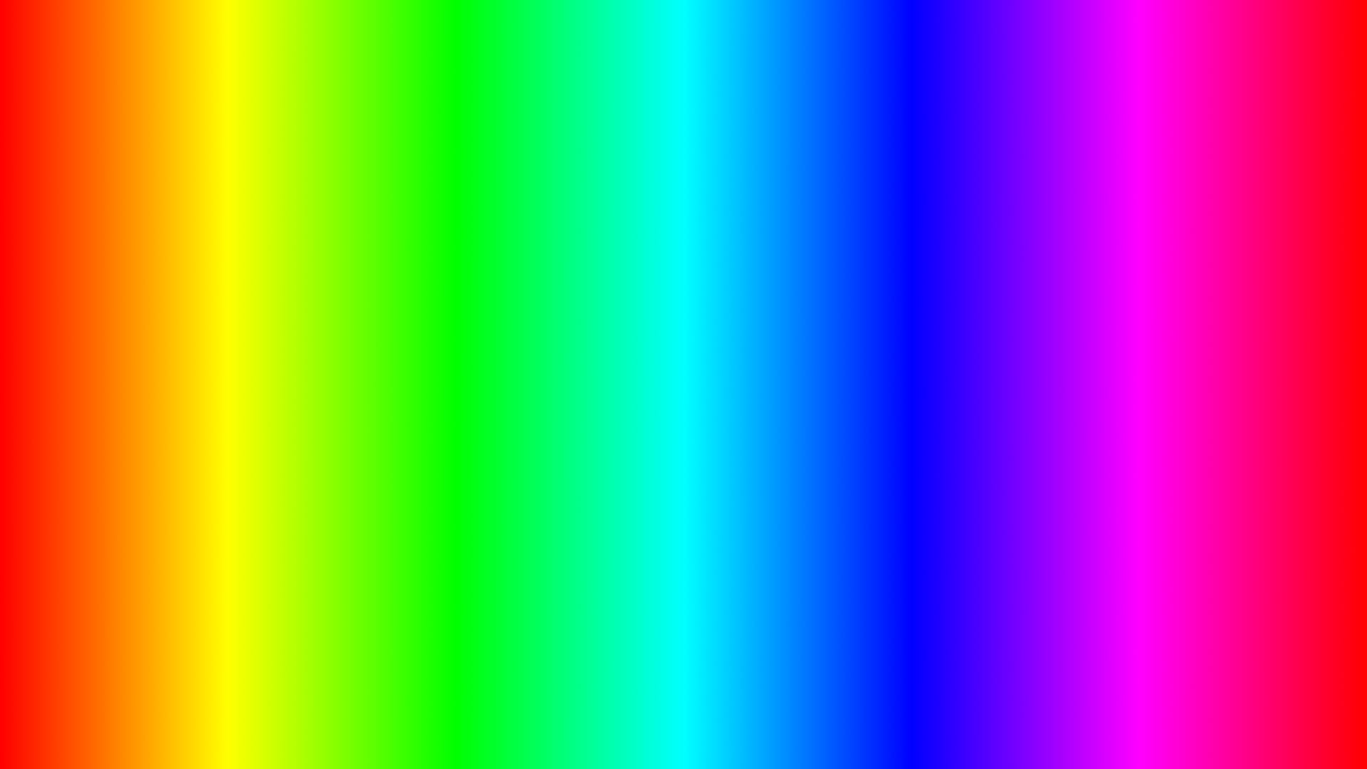
Colour gradient with a linear ramp from 0 (left) to 1 (right) in the hue.
You can create the initial image any way that you like, for example by copying the red channel from a Ramp node to a white Constant node using a Copy node. Or, you could just use an Expression node, and do it all in one (plus make it dynamically fit any format!):
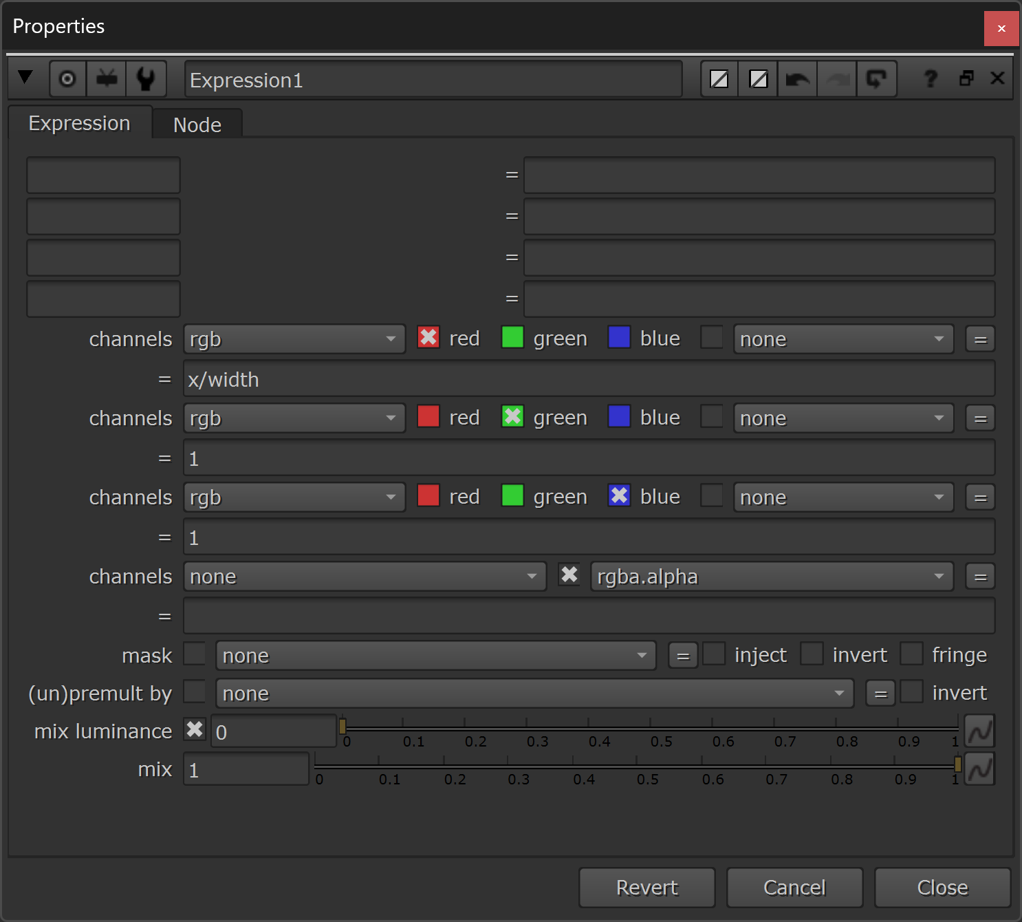
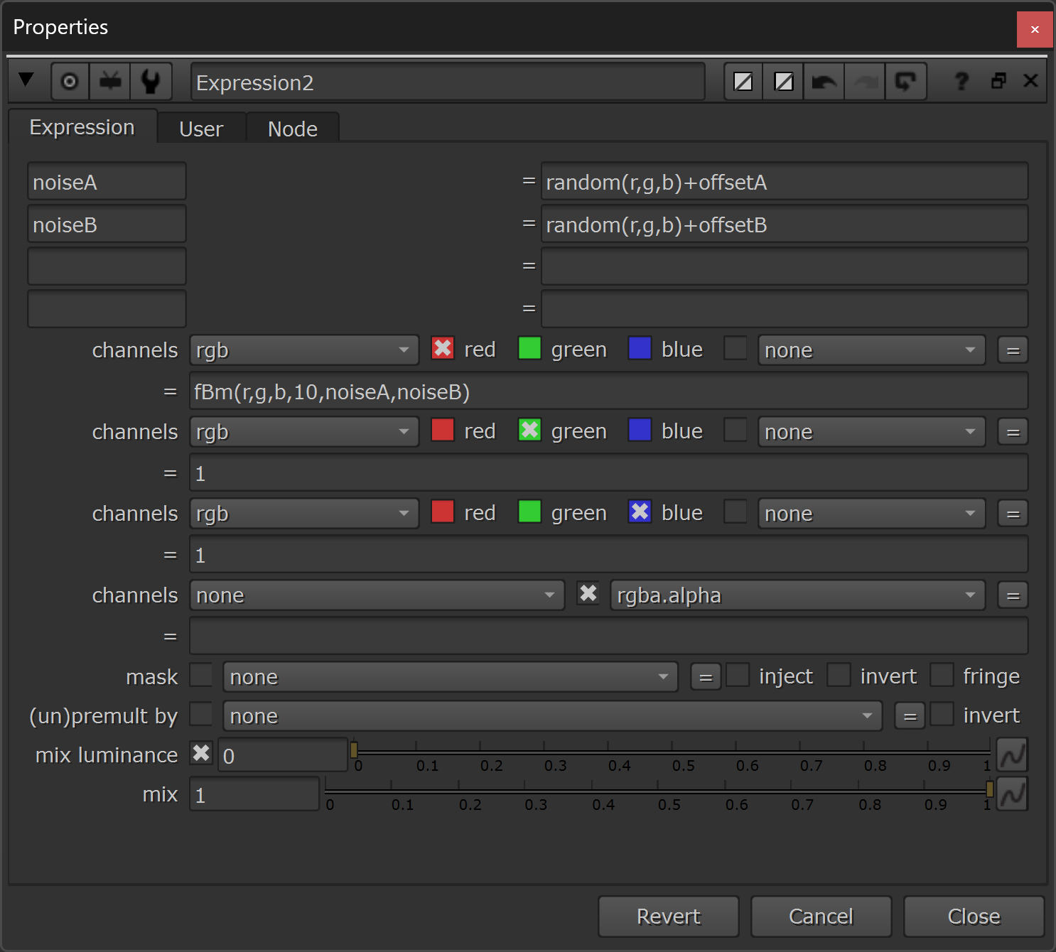
The properties of the Expression node.
The expressions to put in the node are:
Red channel:
x/widthGreen channel:
1Blue channel:
1The initial image will look like this:

A 0-1 ramp along the x-axis in the red channel, and a value of 1 in the green and blue channels.
Next, connect a Colorspace node to this image, and set the input to HSV and the output to Linear (RGB) in the Colorspace node's properties:
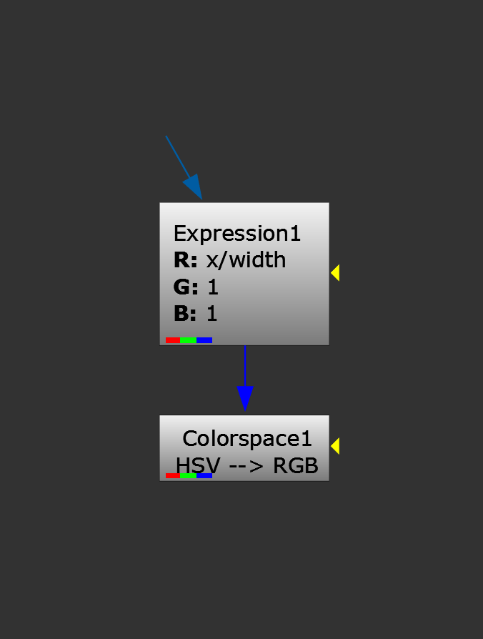
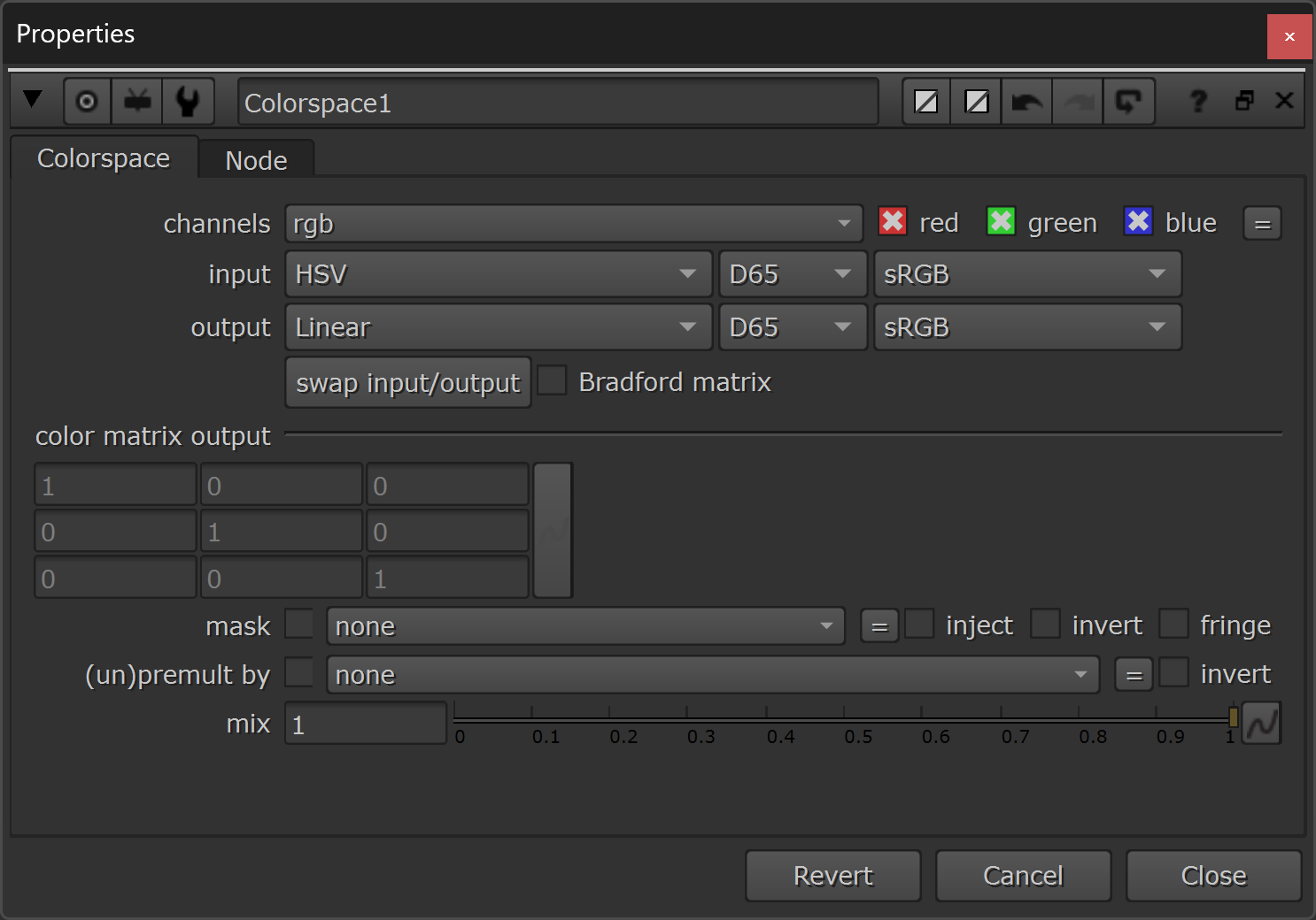
Adding a Colorspace node to convert the ramp into a rainbow gradient.
Okay, now we’ve got the full spectrum rainbow colour gradient which we saw above.
However, we may want to choose a narrower range of colours from the gradient to display in our iridescent effect, and so we’ll need to be able to offset and limit the range of the gradient.
We can do that by placing a Grade node in between the Expression node and the Colorspace node, and having it only affect the red channel (i.e. the hue):
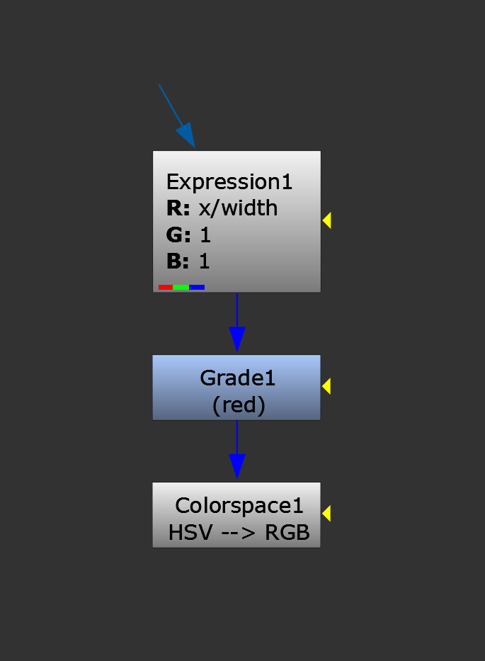
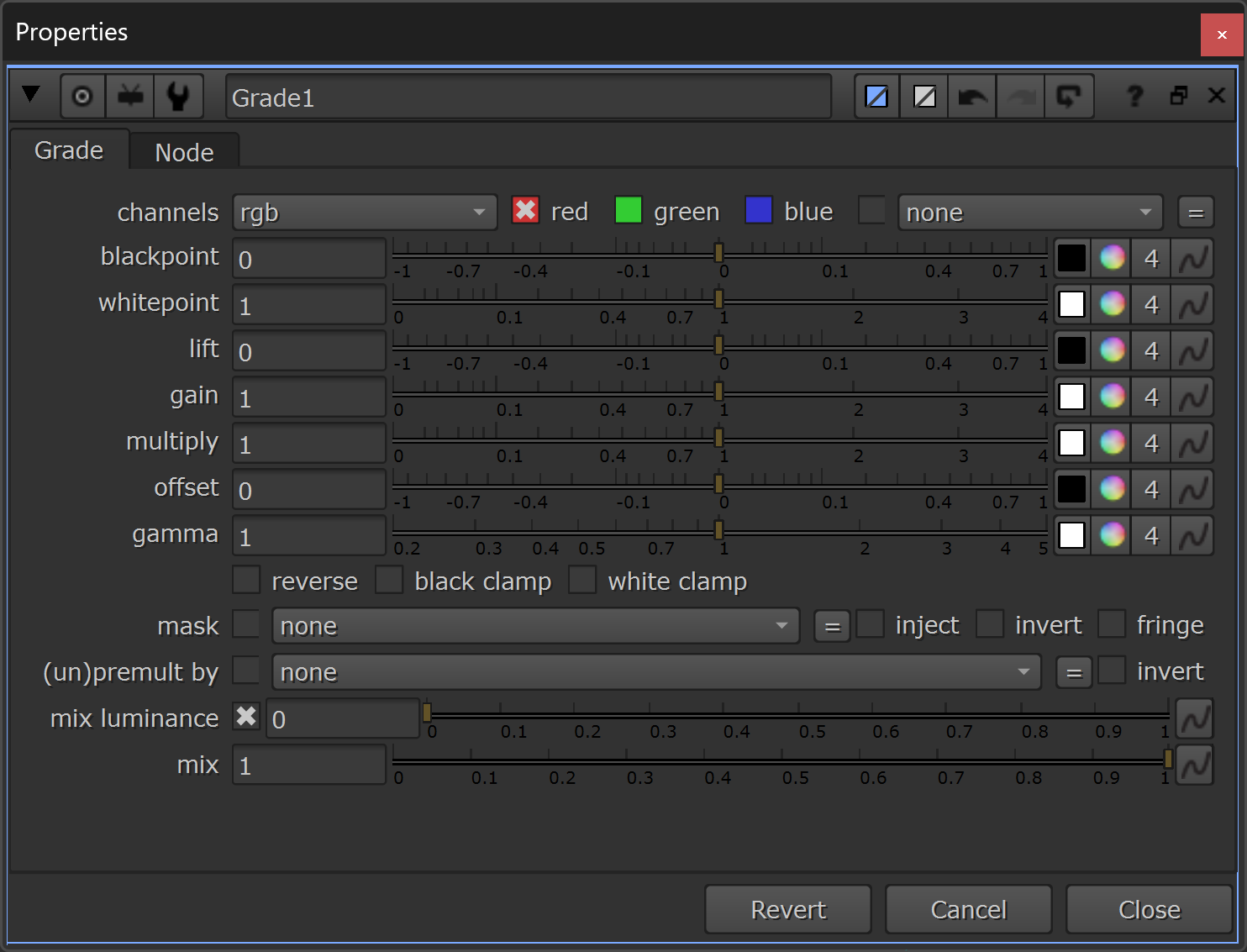
Adding a Grade node to customise the colour gradient.
By adjusting the offset in the Grade node, you can shift the gradient left and right. (Remember, values above 1 and below 0 repeat the hue pattern).
And by adjusting the multiply, you can compress or expand the gradient, letting you hone in on the colours that you want in your iridescent effect.
In the video below, I demonstrate how it works and hone in on a narrower, three-colour range:
Now, with this little setup, we can swap out the Expression node for any input which has a 0-1 ramp/values in the red channel, and a value of 1 in the green and blue channels, and the setup will map the rainbow colours that we choose with the Grade node onto that ramp/those values.
To create iridescence, we need a 0-1 control matte that represents the angle between the surface of an object and the camera.
Control Matte
Enter: facing ratios, a.k.a. the fresnel pass.
This pass contains exactly what we described above: a 0-1 matte that represents the angle between the surface of an object and the camera.
You may get this pass in your CG renders from the lighting department. If not, follow the two links above to learn different ways of generating the pass yourself in Nuke.
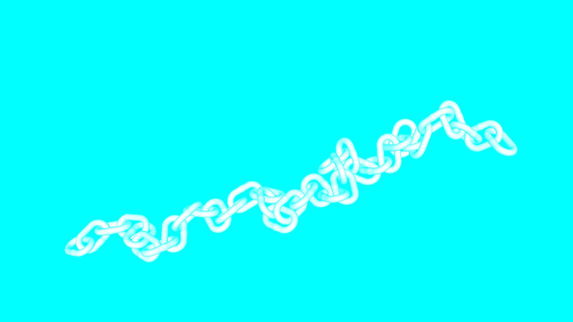
To better show how it all comes together, let’s use a render of a chain as an example:
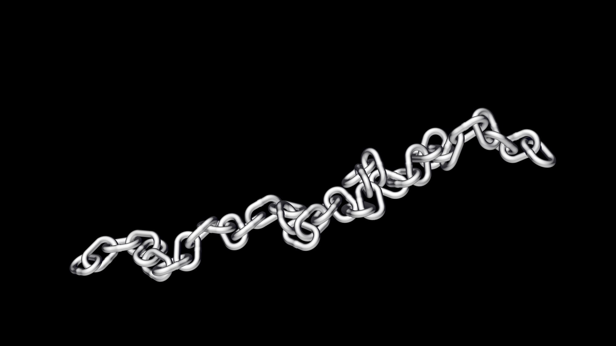
Plain chain render.
The facing ratio matte for the chain looks like this:
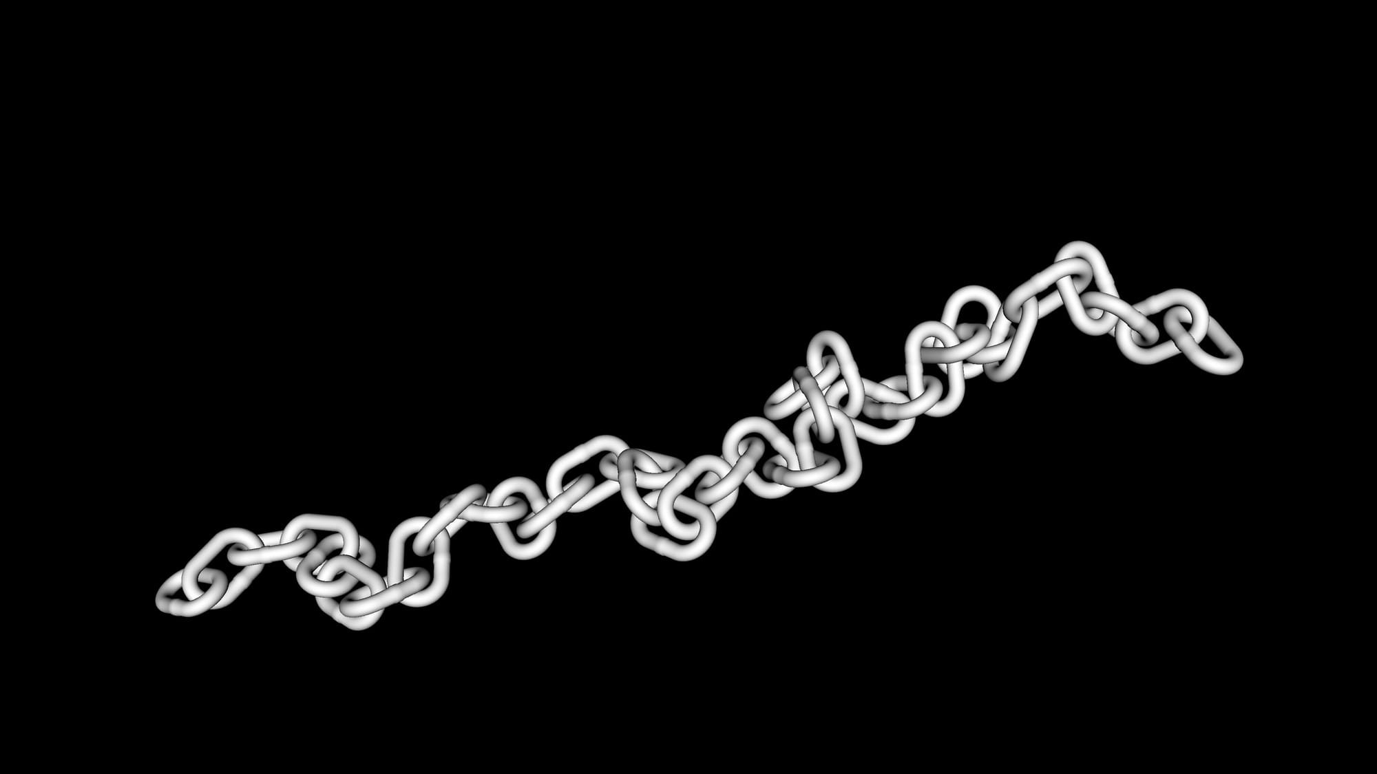
The facing ratio matte is white where the surfaces are facing the camera and black where they’re perpendicular to the camera.
To use it with our little setup, let’s shuffle white into the green and blue channels of the facing ratio matte:
Putting the facing ratio matte into the red channel and putting a value of 1 into the green and blue channels.
By connecting our setup to this, we get a (much too strong) iridescent effect which covers the surfaces of the chain:
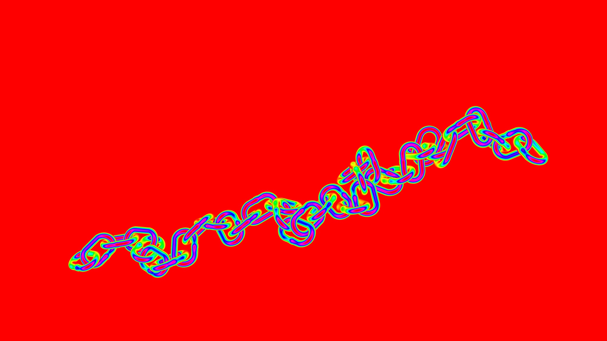
The raw iridescence pass.
To tone down the effect into something more realistic, we can Merge (multiply) it into only the specular AOVs of our render, and leave the rest of the AOVs/beauty as they are.
And, we can also use the facing ratio matte as a mask for that multiplication, so that the effect fades off towards the glancing angles:
The raw iridescence pass multiplied into the specular AOVs of the chain render, masked by the facing ratio matte.
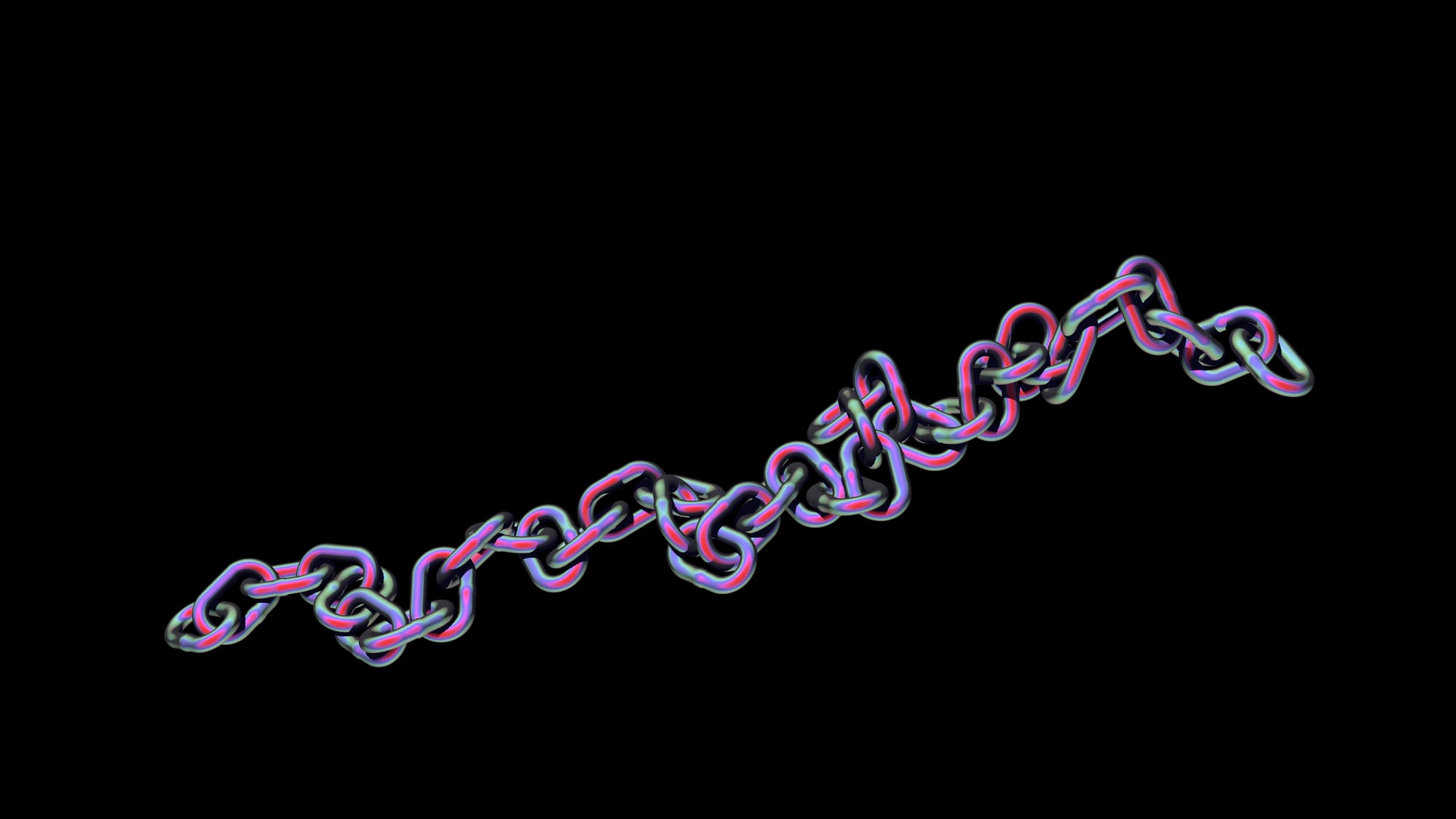
This looks a lot better. Let’s adjust the colours to a range we want by changing the offset/multiply in our Grade node:
Changing the iridescent colours.
This looks quite nice, but the iridescent effect is still very uniform. Every surface that is facing the same way is receiving the exact same colour.
Adding Variation
We can break up this uniform look by multiplying some noise into the control matte (i.e. the fresnel pass/facing ratio matte) with a Merge (multiply), just before the Grade node in our setup.
This can be any noise, but it’s useful to use a noise that tracks with the object, especially when the camera or the object moves.
You could for example use the aPMatte gizmo, or a similar tool, together with a Pref pass to generate 3D noise that sticks to the object.
Like Julius did, let’s make our own 3D noise from scratch so that we can customise it even more.
Shuffle out the Pref pass from the render, and add an Expression node to it.
We’re going to be mixing together two different noise functions: the fBm and the random function. From the Nuke TCL Script Expressions guide:
The fBm function takes up to six arguments (parameters): x, y, z, octaves, lacunarity, gain.
fBm stands for Fractional Brownian Motion. This is the sum of octaves calls to noise. For each of them the noise xyz point is multiplied by pow(lacunarity,i) and the noise output is multiplied by pow(gain,i). For normal use lacunarity should be greater than 1 and gain should be less than 1.
The random function takes up to three arguments (parameters): x, y, z.
The function creates a pseudo random value between 0 and 1. It will always generate the same value for the same x, y, and z. Calling random with no arguments will create a different value on every invocation. The y and z arguments are optional, and if missing, they are set to zero.
So, let’s create some fBm noise, but instead of putting in values for the lacunarity and gain, let’s put in two random functions in order to create more variation in the noise. – Noise patterns within a noise pattern, if you will (or, noiception):
Creating 3D noise based on a position pass.
At the top of the Expression node, I define the two random expressions:
noiseA = random(r,g,b)+offsetA
noiseB = random(r,g,b)+offsetBThese will simply make a random number between 0 and 1 based on the red, green, and blue channel’s values (i.e. the position of the object), and add an offset to it.
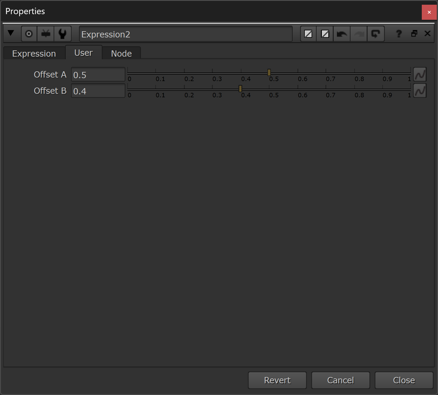
– I created two Floating Point Sliders named offsetA and offsetB, which let me adjust this offset more easily.
Then, in the red channel, I added the fBm expression:
fBm(r,g,b,10,noiseA,noiseB)– which creates the main noise pattern based on the red, green, and blue channel’s values (i.e. the position of the object), using 10 octaves (you could create another noise to drive this as well, if you like), and with the lacunarity and gain driven by the two random expressions.
The green and blue channels are simply set to 1.
Blur the result of this to taste, and Merge (multiply) it with the control matte (i.e. the fresnel pass/facing ratio matte), just before the Grade node in our setup.
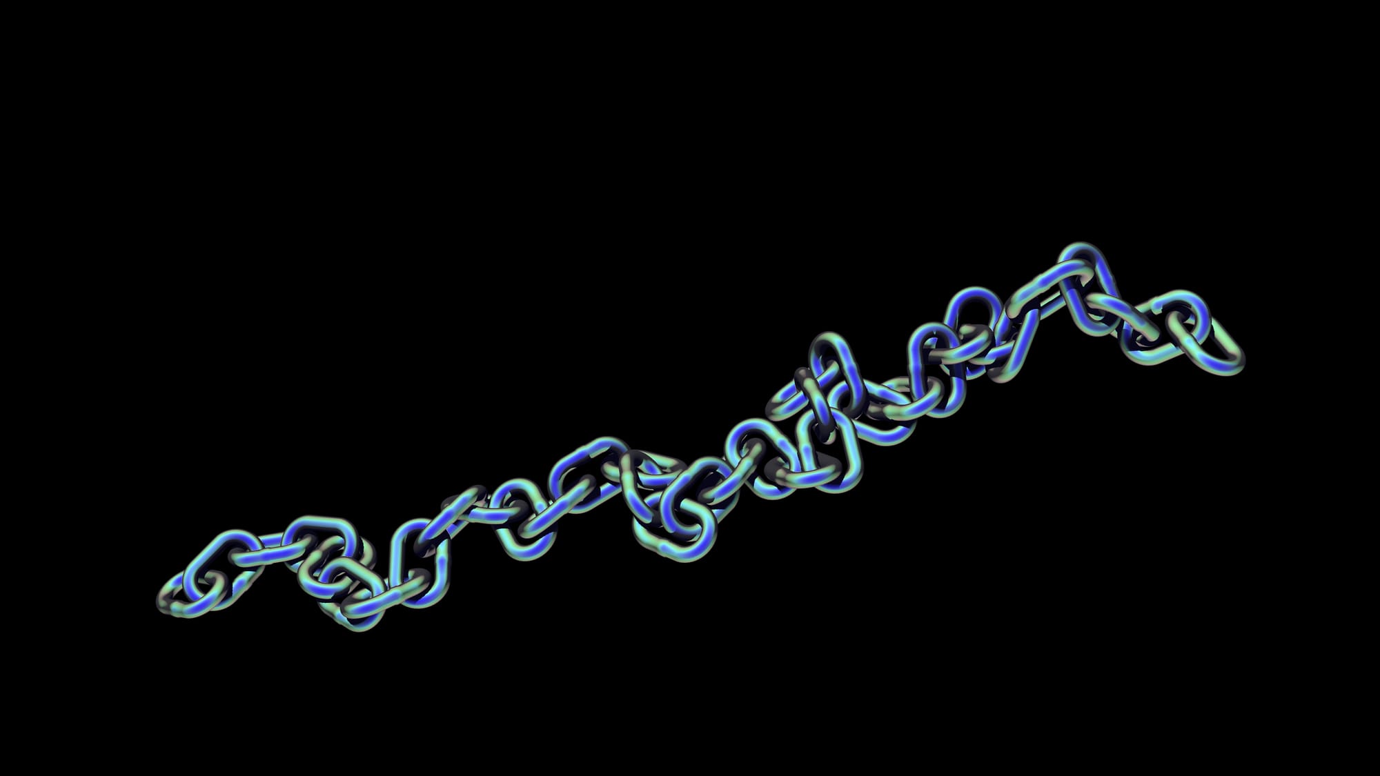
Now, the iridescence has a more natural variation to it:
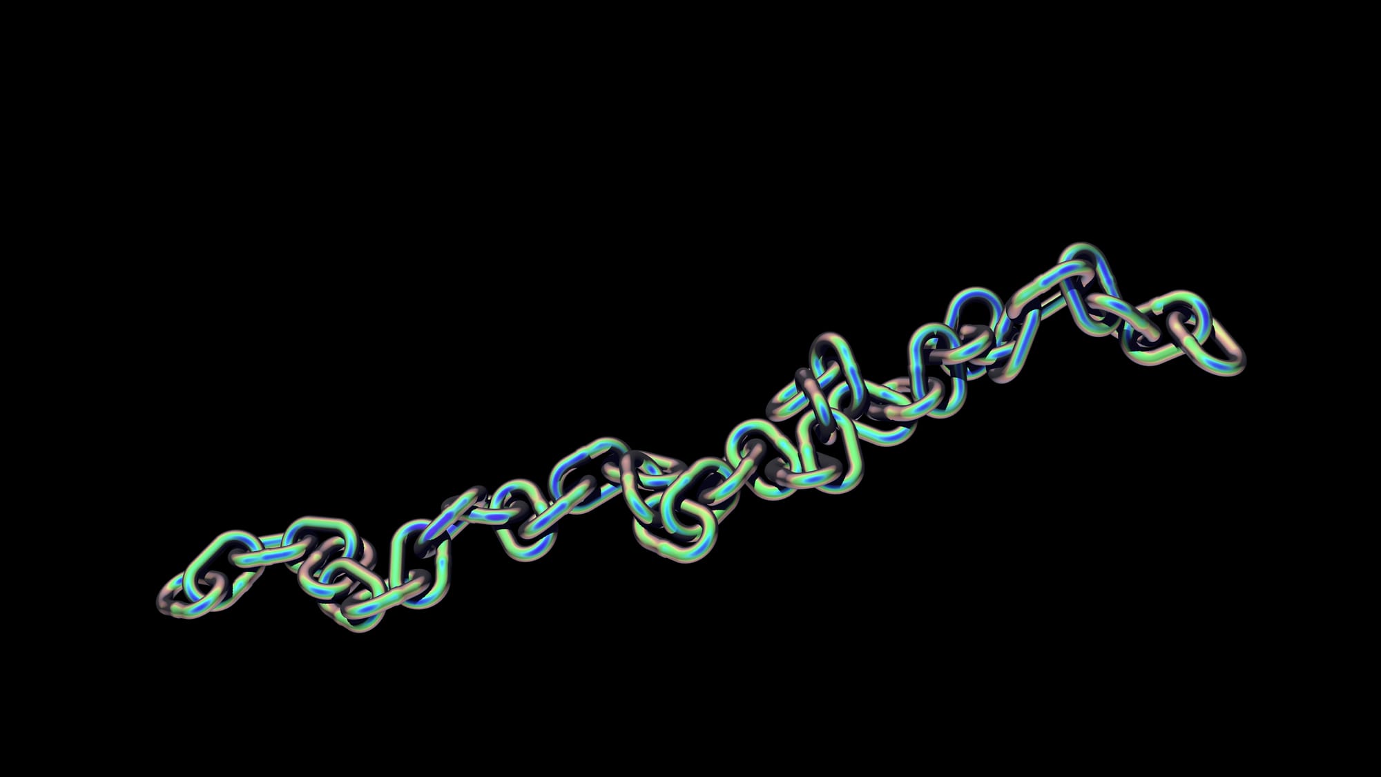
Adding some natural variation to the iridescence by using noise.
Obviously, I’ve gone for a quite strong, anodised metal look here. Typically, you’d mix back the iridescence further and constrain it more using the facing ratio matte.
Have fun with it and experiment!
I hope you found this tutorial useful. For more Nuke tips & tricks, see Nuke.