Upgrade Your Light Wraps Using Facing Ratios In Nuke
How to produce a more physically accurate light wrap by treating it with a facing ratio pass…

How to produce a more physically accurate light wrap by treating it with a facing ratio pass.
The Bane Of Light Wraps
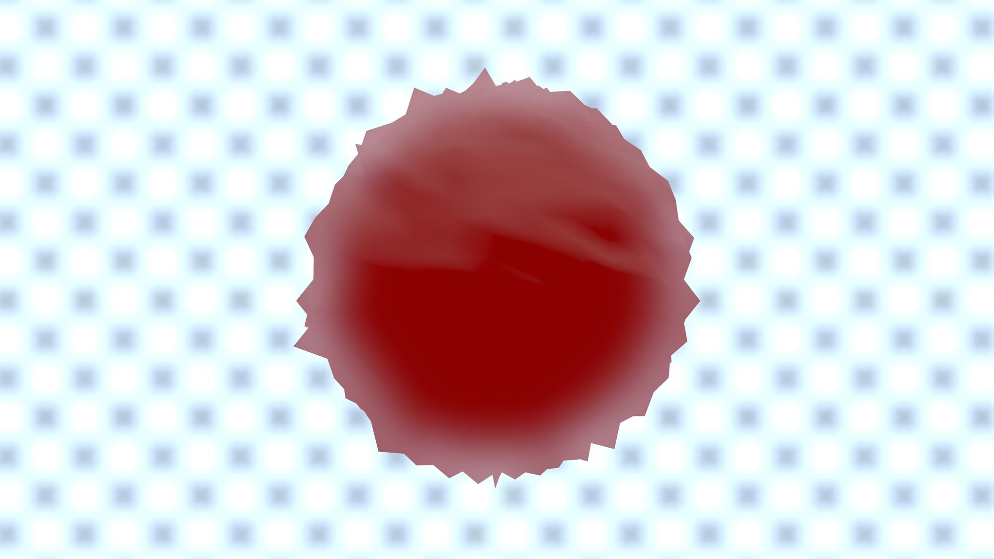
A common issue when compositing is that light wraps often have that soft, undefined inner edge that looks a bit fake. See for example the soft ring shape in the object below:
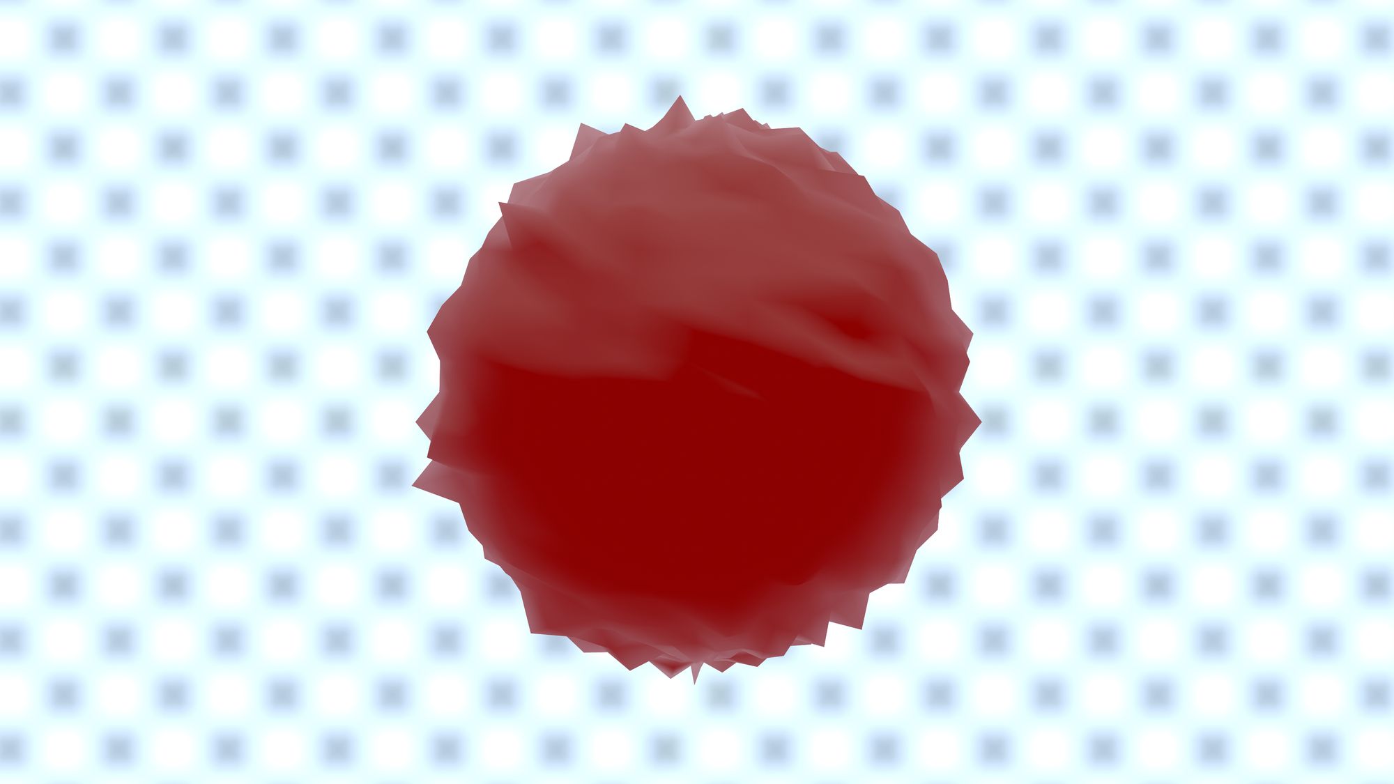
The exact same light wrap treated with a facing ratio pass looks much more natural, and more accurately reacts to the surfaces of the object:
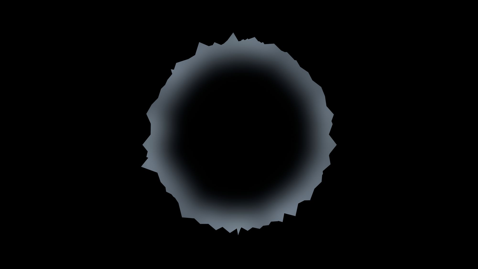
Let us take a closer look. Here is the first light wrap effect isolated:
And here, that same isolated light wrap effect is treated with a facing ratio pass:
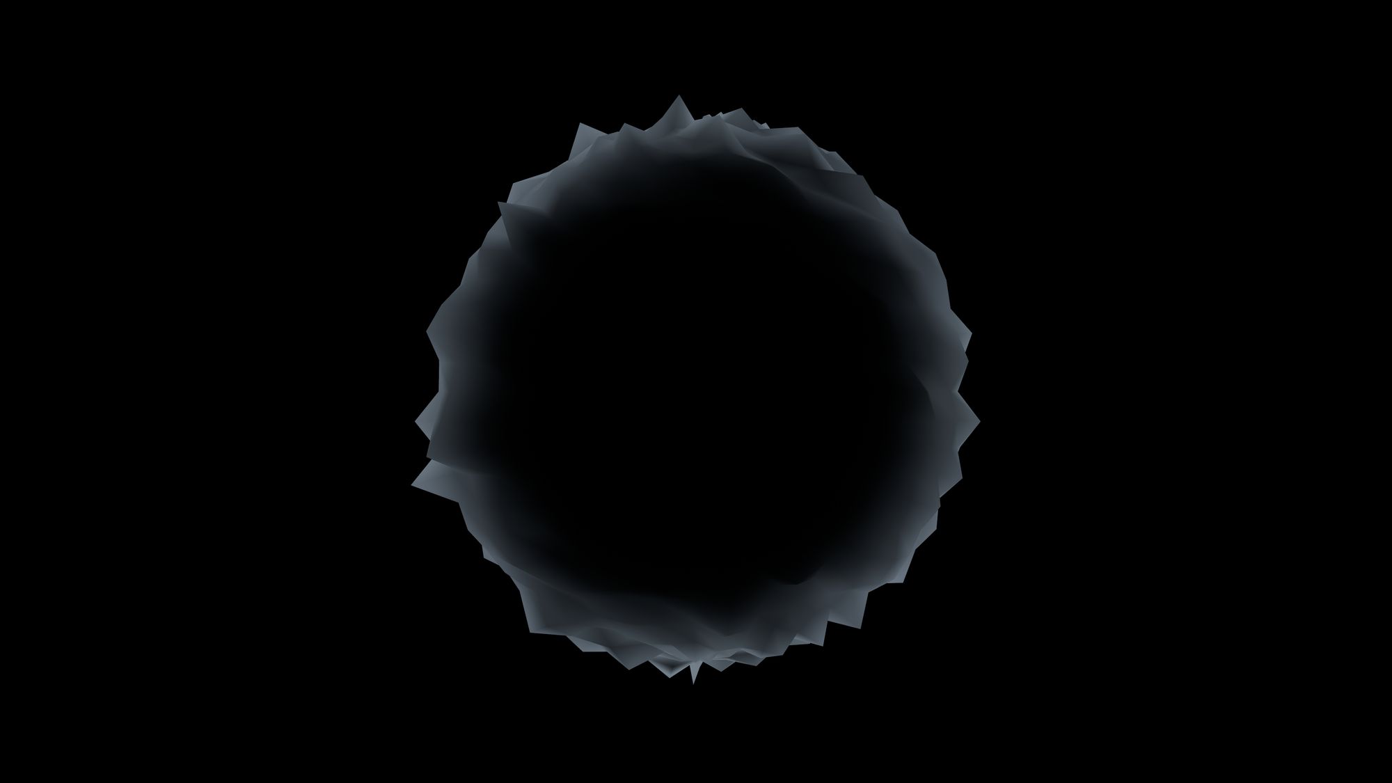
The difference is quite impressive. So, how can you do this with your light wraps? Let us look into the aforementioned facing ratio pass.
What Is A Facing Ratio Pass
A facing ratio pass is a matte which describes the orientation of the surfaces of an object relative to the camera. If a surface is facing directly towards the camera, the matte will be white (have a value of 1) in that area of the image. If a surface is facing 90 degrees perpendicular to the camera, the matte will be black (have a value of 0).
Surfaces that are angled somewhere between will have grey values between 0 and 1. (If you would have been able to see the surfaces facing away from the camera, their values would have been negative, down to -1 for directly opposite-facing surfaces).
And so the matte represents a facing ratio – a ratio of how much a surface is facing the camera – from 0 to 1.
You may already be getting this facing ratio pass in your AOVs from your lighting artist. If not, you can generate it yourself in Nuke. Let us look into how to achieve this.
Back To Basics
To understand how to make a facing ratio pass, it may be useful to first refresh your memory of some A-level mathematics. Forgive me if it starts out too basic, I hope it will all make sense shortly.
Axes In A Coordinate System
A 3D coordinate system such as the one in Nuke has (as the name suggests) three dimensions. Each dimension is illustrated by its own axis: the X axis, the Y axis, and the Z axis. These are all 90 degrees perpendicular to each other and represent different directions in 3D space.
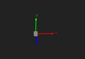
Using the Axis node to visually represent the three axes in Nuke’s 3D coordinate system.
Which axis points in which direction is arbitrary. In Nuke, relative to camera space, the X axis points left and right, the Y axis points up and down, and the Z axis points toward and away from us.
Where the axes all intersect is called the origin. If you assign values along each axis to describe how far along the axis you are, the origin would be the starting point, and have a value of 0 along all three axes. (X=0, Y=0, Z=0).
The values going from the origin and to the right along the X axis (relative to camera space) are positive, and the values going to the left from the origin are negative. And similarly, the values going up on the Y axis from the origin are positive, and the ones going down are negative. The values going toward us on the Z axis are positive and the ones going away from us are negative.
World Space Versus Camera Space
How the 3D coordinate system is orientated depends on your frame of reference.
In world space, the X, Y, and Z axes are all locked in relation to the world. They are absolute. As the camera moves around, the axes stay put in the world. If the Z axis points toward/away from the camera, and you rotate the camera 90 degrees sideways, now the Z axis points left and right in relation to the camera. Instead, now the X axis points toward/away from the camera. (Because the camera moved while the axes did not).
In camera space (a.k.a. screen space), the X, Y, and Z axes are all locked relative to the camera/screen. As the camera moves around, the axes follow along so that they always stay the same relative to the camera. The camera essentially becomes the (moving) origin. The X axis always points left and right on the screen, the Y axis always points up and down, and the Z axis always points toward and away from the screen. No matter where the camera points, the axes follow. If the Z axis points toward/away from the camera, and you rotate the camera 90 degrees sideways, the Z axis still points toward/away from the camera.
Normals
Normals are vectors pointing along the X, Y and Z axes. They describe where a surface is facing. They always point 90 degrees outward from the face of a surface. From the normals you can derive the rotational values of the surface.
Normals are usually rendered with reference to world space. When we render a 2D representation of normals (such as the normals pass in the CG render), each vector component is rendered to a separate colour channel:
The red channel will have values for the X component of the vectors.
The green channel will have values for the Y component of the vectors.
The blue channel will have values for the Z component of the vectors.
Like with the world space axes, the world space normals also stay locked in relation to the world when the camera moves around. If you align the camera to the Z axis and look at the normals, the surface of an object facing toward the camera will look blue (because that surface is facing along the Z axis). It will have positive values in the Z component of the normal vectors, which is in the blue channel. But if the camera rotates around 90 degrees sideways, the surface that is now facing the camera will look red (because that surface is facing along the X axis). It will have positive values in the X component of the normal vectors, which is in the red channel.
If you instead convert the world space normals into camera space normals, now the surfaces of an object facing the camera will always look blue. They will have positive values in the Z component of the normal vectors, which is in the blue channel. The surfaces that are not directly facing the camera will have lower and lower values in the blue channel, down to 0 for the surfaces that are 90 degrees perpendicular to the camera. (If you would have been able to see the surfaces facing away from the camera, their values would have been negative).
Hopefully, this sounds familiar. By using camera space normals you can make a facing ratio pass, describing an object's orientation in relation to the camera. With this, you can turn a generic light wrap into a much more physically accurate light wrap.
How To Create A Facing Ratio Pass
You can use your camera to convert the world space normals into camera space normals, which are needed for making the facing ratio pass. The World matrix in the camera’s properties describes the camera’s translation, rotation, scale, etc. in 3D space, relative to the origin.
It is a 4x4 matrix, which means the rotation happens in the top left 3x3 elements. From a to i – highlighted in blue – in the illustration below:
If you invert the camera’s World matrix and apply it to the camera, you bring the camera back to the origin. Essentially going from camera space (relative) to world space (absolute).
If you instead apply the same inverted matrix to the normals (which are in world space), you then bring them into camera space. Meaning the Z component (blue channel) of the normal vectors will always be facing the camera.
You can do this using a ColorMatrix node. Link the Camera’s World matrix to the matrix in the ColorMatrix node and tick the invert checkbox to invert it. Keep in mind, the Camera’s World matrix is a 4x4 matrix and the ColorMatrix node’s matrix is a 3x3 matrix. Luckily, we are only interested in the values for the rotation. (Since normals describe which direction a surface is facing). Which means you will have to link the values as follows:
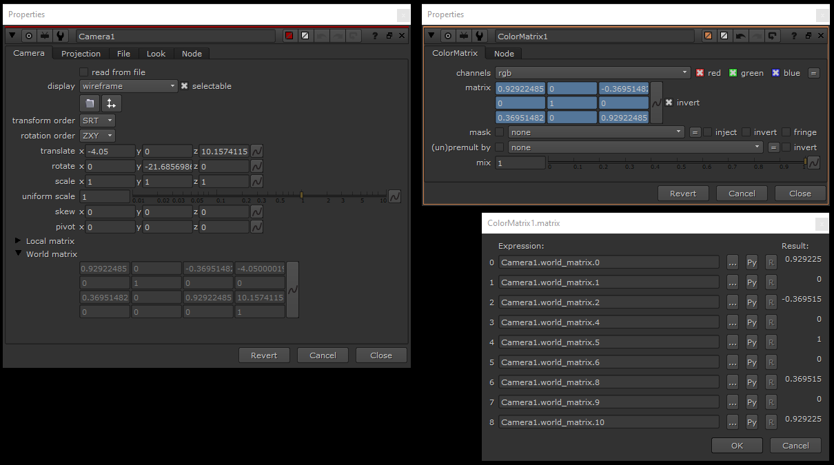
💡 Note that you will be skipping world_matrix.3, world_matrix.7, and world_matrix.11 (m, n, and o in the previous matrix illustration, respectively), and the whole bottom row of world_matrix.12 to world_matrix.15 (j, k, l, and p, respectively), in order to link the 4x4 matrix to the 3x3 matrix.
Apply this ColorMatrix node to your normals pass and you will have created a facing ratio pass in the blue channel.
How To Use The Facing Ratio Pass
Once you have generated the facing ratio pass, invert the blue channel. That is because you want the surfaces that are facing the camera to receive less light wrap than the surfaces that are at an angle to the camera.
Imagine for example a shoulder with a bright light behind it. To be physically accurate you would want more light wrap around the top of the shoulder than on the front of the shoulder. (Because the front of the shoulder is more occluded from the light than the top is).
Then, shuffle the blue channel into the red and green channels because you will be multiplying the RGB channels with the light wrap.
Next, add a Grade node to be able to adjust the falloff and strength of the matte. Make sure to tick black clamp and white clamp, so that all the values in your facing ratio pass stay between 0 and 1.
Finally, multiply the result with your light wrap (the effect only) before adding that to your comp with a Merge (plus). That way, you will get a light wrap that correctly adjusts based on the angle of the object in relation to the camera.
A Convenient Tool
I have wrapped everything in this tutorial up into a handy tool together with an example scene which you can download below.
Interface
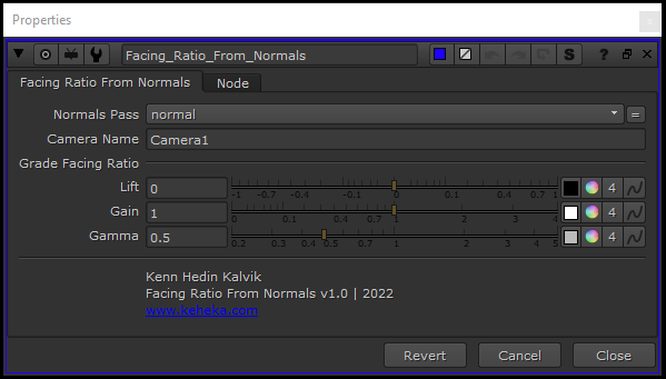
The controls are simple:
Connect the node to your normals and select your normals pass in the drop-down menu.
Type or copy/paste in your camera name.
Adjust the grading on your facing ratio matte as necessary.
Multiply the output of this node with your light wrap (effect only).
Not Just Light Wraps
While using the facing ratio pass to upgrade light wraps is perhaps the more common use for the pass in compositing, the pass is really versatile and can be used for many interesting things:
You can multiply the output of the node with your CG reflections using a Merge (multiply) to get a Fresnel effect.
You can use it as a matte for colour grading your CG render, for example to make a two-tone tinted car paint effect.
You can create fake refractions using an IDistort and normals, and then use the facing ratio pass to add more realism to the lighting and visibility through the object.
You can make multiple facing ratios with different grades to create a heat map/heat vision effect.
You can use the facing ratio or the inverted facing ratio as a mask for the opacity of an object and animate it to create a ghostly effect.
You can use it in the same way as with the light wrap but with a glow or other light source instead.
The sky is the limit. I am sure it is possible to build a toon shader look using the pass with a more advanced setup. Maybe you have some other cool ideas for how to apply the facing ratio!
I hope you found this tutorial useful. For more Nuke tips & tricks, see Nuke.