Creating Parallax In Nuke
A closer look at how parallax works, and how we can create and/or match the effect in Nuke…
A closer look at how parallax works, and how we can create and/or match the effect in Nuke…
Parallax
Parallax is the apparent shift of an object’s position relative to more distant background objects when viewed from different perspectives.
The change in perspective, or viewpoint, is due to the position/motion of the observer, of the observed, or both:
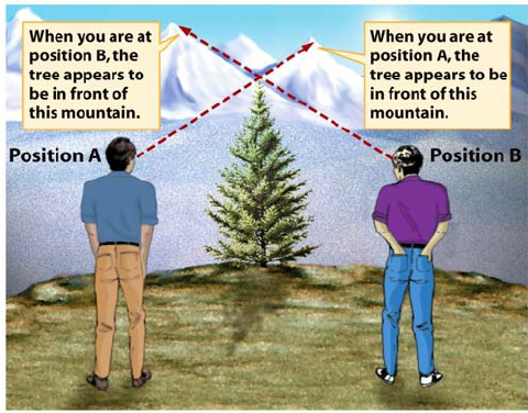
A change in viewpoint leads to different views. (Source).
In a stereoscopic context (i.e. how we see the world with our eyes), the change is due to the difference in the position of each eye. – Our eyes see an object from slightly different angles.
You can easily see this stereoscopic parallax effect for yourself by holding out one of your hands in front of you, and looking at for example your index finger against the background with one eye open and the other eye closed.
Then, open the previously closed eye while simultaneously closing the previously open eye, and the finger will appear to move against the background:
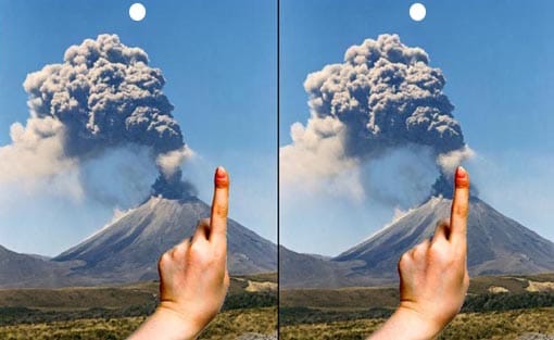
Stereoscopic parallax. (Source).
– Alternate blinking with each eye, and your finger will appear to bounce left and right.
The closer an object is to the observer, the larger the apparent shift against the background. I.e. the larger the parallax angle.
And so, foreground objects will seem to move faster relative to background objects (this is also true even if they would travel at the exact same speed in reality):
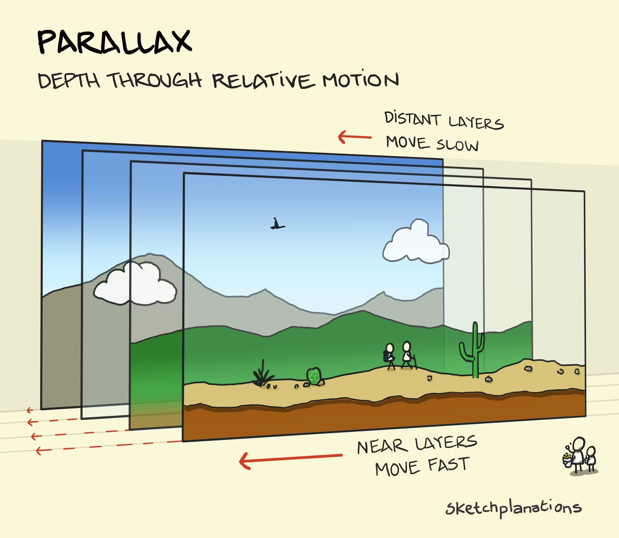
Depth through relative motion. (Source).
In fact, that is the basis for how 2D side scroller video games achieve a sense of depth/perspective:
Foreground layers move faster than background layers. (Source).
Here’s a short video that nicely shows how it works:
This is why 2D games feel 3D (but aren't). Parallax.
Interesting side note – Parallax is also used to determine the distance to stars:
By measuring the extremely small observed shift of a star against the background of distant stars – at the largest time interval of about six months, when Earth arrives at opposite sides of the Sun in its orbit – the distance to the star can be calculated using trigonometry.
Stellar parallax can also be determined by comparing measurements from Earth and from a distant spacecraft, giving us a much more visually clear distinction in the position due the the distance between the observers – which allows us to see the parallax without instrumentation:
Parallax of Proxima Centauri as observed from NASA’s New Horizons spacecraft and from Earth. (Source).
We may not need to accurately measure stellar distances, but for us compositors, understanding how parallax works is still essential knowledge.
– Because parallax is an effect that we have to mimic in our shots to create a sense of depth.
There are several ways to do this:
Parallax In Nuke
To convincingly composite an element (e.g. a CG render, DMP, 2D smoke element, patch, or similar) into a shot, we have to position the element at, and track the element to, the correct depth plane.
– I.e. the element needs to be placed at the correct distance from the camera, and behave as if it were filmed from that distance with the same camera.
To do that, we have to first identify the depth plane where we want the element to sit.
Like we saw in the diagram earlier, different depth layers appear to move at different speeds from the camera’s point of view.
And so, if you want to position your element near a background mountain, keep in mind that that’s a different depth plane to a foreground rock, and your track for the foreground rock will likely not work for your background mountain.
It’s often more intuitive when looking at a 3D scene:
Camera Track
Ideally, you would get a camera track for your shot, plus locators, a point cloud, and/or proxy geometry of the environment, so that you can set up a 3D scene in Nuke and place your element at the correct depth plane.
First, it’s important that your camera is accurately tracked to your scan. To correctly match the motion parallax at various depths in the scan, the CG camera has to match up with the real camera.
– Even small inaccuracies in the track can become noticeable when compositing your element.
Then, to put a 2D element into a 3D scene, you can project it onto a Card or other geometry that is positioned at the correct depth plane.
There are several things you can do to help place your Cards/geometry correctly:
Positioning Cards/Geometry
If you do your own camera tracking using the CameraTracker node in Nuke, you can export a CameraTrackerPointCloud to help with positioning any Cards or other geometry in 3D space for projection purposes.
(Or, you can create the Cards/geometry directly in the 2D view using the create menu).
You can also create a point cloud by using a PointCloudGenerator node connected to your footage and to your camera. This will typically create a much denser and more easily readable point cloud than the one that you can export directly from the CameraTracker node:
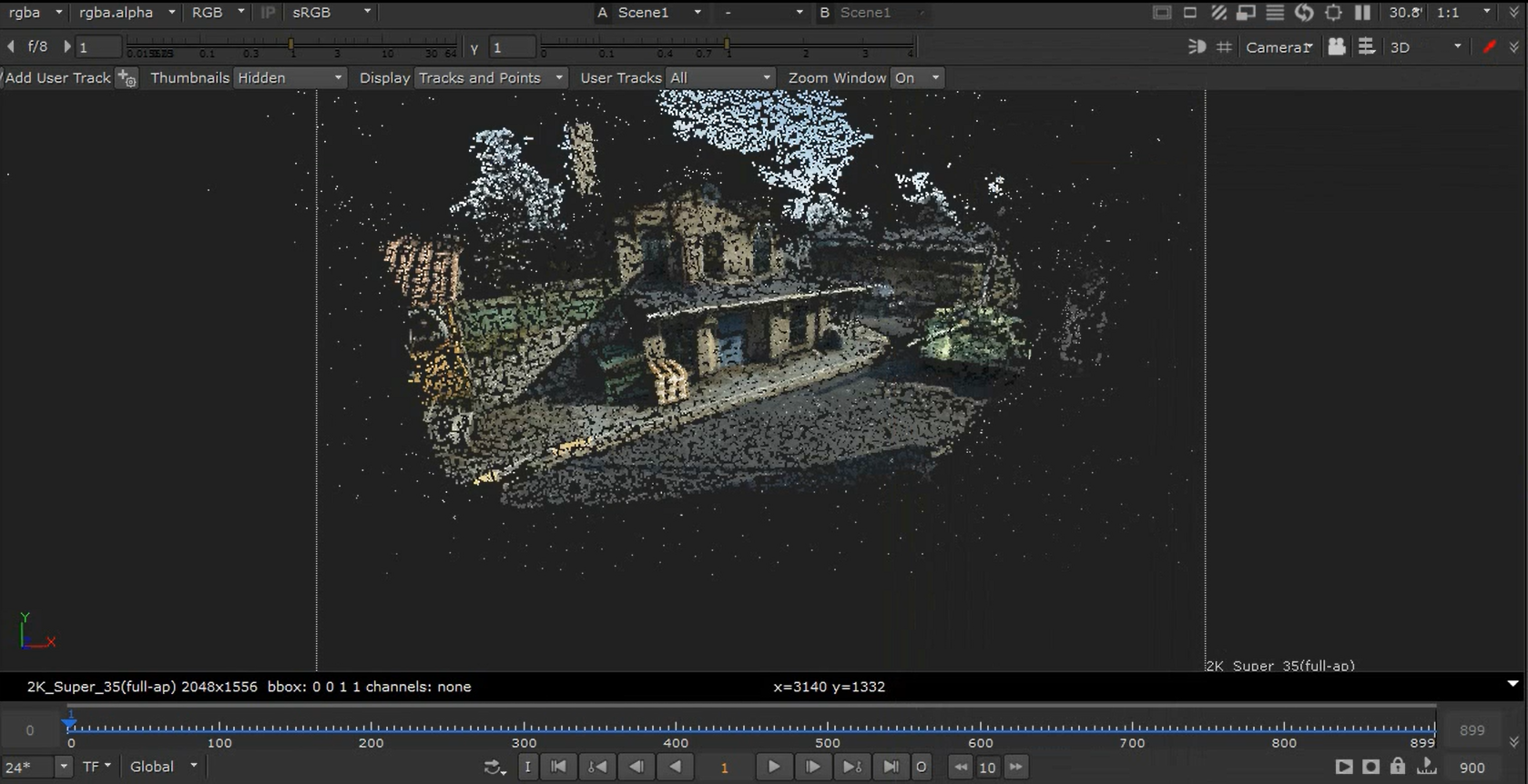
A point cloud generated by the PointCloudGenerator. (Source).
You can even create a point cloud from a CG render containing world/reference position and normal AOVs using the PositionToPoints node.
Or, you can create a point cloud from a Deep render and the Camera by using the DeepToPoints node.
If you get a camera track from your matchmove department, you may also get locators or proxy geometry of the scene to help with the positioning. And/or, there may be LIDAR geometry available.
Note that LIDAR geometry tends to be very heavy, so disable the ReadGeo/GeoImport node when not in use. – In fact, disable or delete any geometry that isn’t being used in your comp.
Another way to accurately position Cards at the right depth plane is to use this technique:

Scene Scale
Note that when you’re using cameras and position passes from different software, you’ll have to ensure that your scene scale is correct.
Different 3D software use different units of measurement. Maya uses centimetres by default, while Houdini uses metres, for example. Others may use a different unit, like decimetres, or one of the imperial units.
Unless you’re using the new 3D system (which is currently in beta and not widely adopted yet), Nuke just equates any value as being equal to one unit in 3D space. So, if you import cameras, geometry, and/or renders from different software, you may have to scale them up or down so that they align with each other.
For example, if you have a camera from Maya (cm) and a CG render from Houdini (m), you can scale up the utility passes (such as the position pass) in the Houdini render by a factor of 100 to get the correct scale in relation to the Maya camera in Nuke.
Or, you can scale down the Maya camera by a factor of 100 to get the correct scale in relation to the Houdini render.
To scale your CG render’s utility passes, you can connect a Multiply (math) node and multiply the passes up or down to scale them accordingly.
To scale your geometry or camera, you can plug an Axis node into a TransformGeo node, or directly to the Camera, and adjust the uniform scale value in the Axis. (Leave all other values in the Axis node at default – it should stay at the origin, 0, 0, 0, for the scaling to be correct).
To scale a Deep render, connect a DeepTransform node and adjust the zscale value. Note that the zscale value works inversely to a Multiply. So if you want to scale the Deep up by 100, set the zscale to 1/100 = 0.01.
Using the tips above, make sure that you have got the right scene scale, and – using a point cloud/proxy geometry/etc. of the scene – position your cards or geometry at the correct depth in relation to your camera in 3D space.
If you project a building that’s supposed to be 20 metres away on a card that is 2 metres away, the motion parallax won’t be correct.
You’ll often be able to spot if something’s wrong with the parallax:
Check The Parallax
Check that objects move correctly in relation to each other.
As mentioned earlier, objects further away from the camera generally move slower across the frame than objects near the camera.
If they’re not, it might just be because your Cards/geometry are incorrectly placed in depth – if so, try adjusting their distance from the camera.
And, make sure that objects move at realistic speeds depending on their distance from the camera, especially when you’re animating them yourself. A car in the far background wouldn't travel the same distance across the frame as an airplane would in the same amount of time, for example.
Also, keep the point of fixation in mind. Any static objects beyond the object that you're fixating on will move relatively in the frame in the direction of the camera motion. Any objects nearer than that distance will move in the opposite direction of the camera motion:
Point of fixation example.
When fixated on the red sphere in the centre and moving the camera, the green foreground spheres move in the opposite direction to the camera motion in the frame, while the blue background spheres move in the same direction as the camera motion in the frame.
Another parallax issue you may find is that projecting images onto Cards can sometimes betray the parallax:
Shaping Cards
Cards are flat, and most objects in the real world are not.
You can use bicubic deformation to give some shape to your Cards, and potentially avoid the issue of the projections looking flat in your scene.
– If you were projecting a leaf onto a Card, for example, you could use bicubic deformation to make the Card concave or convex.
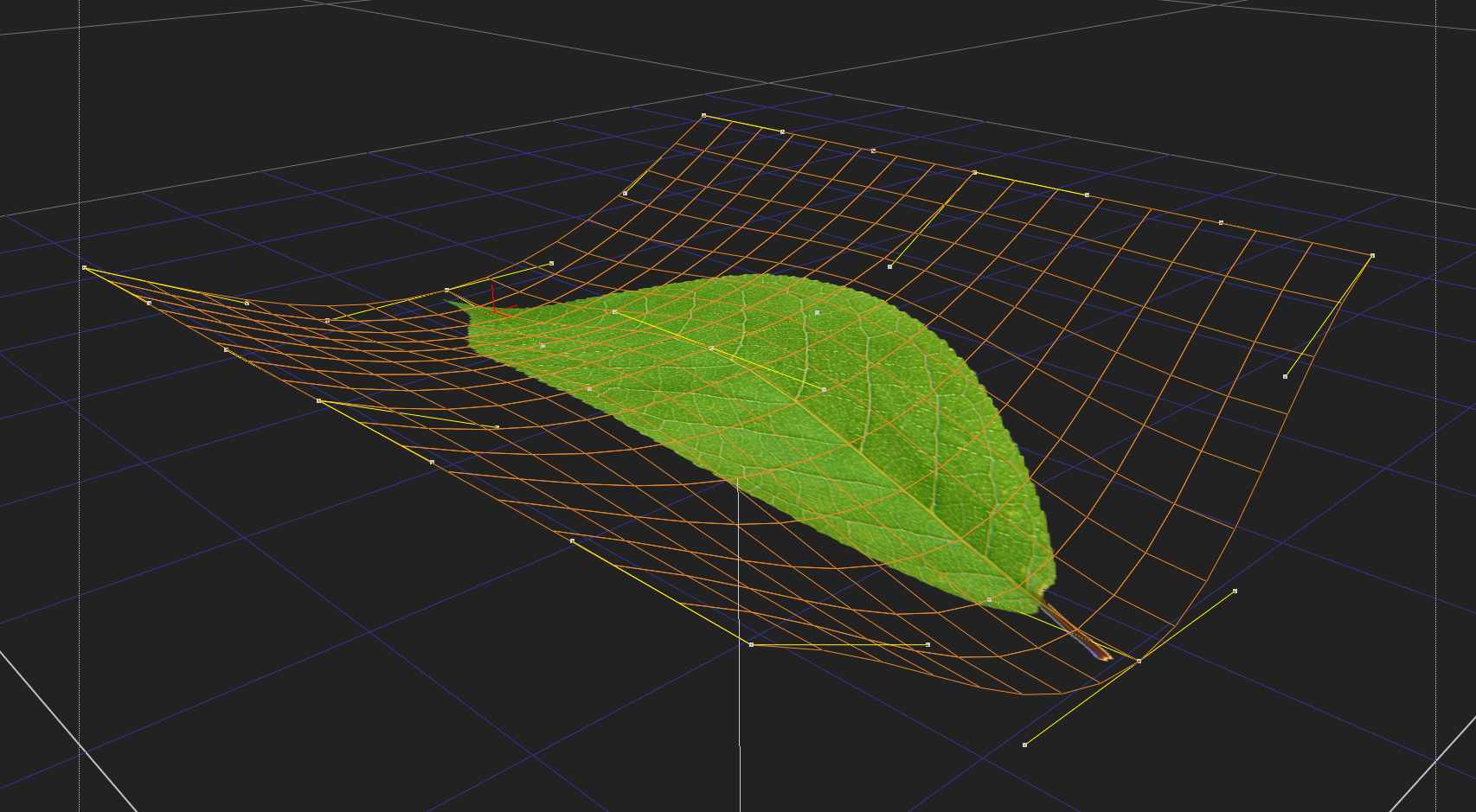
Shaping a Card using bicubic deformation.
This technique is very useful for creating basic terrains or any sort of simple projection geometry.
Speaking of simple projection geometry:
Skies
Skies are generally so far away from the camera that you can often just project them onto a very large Sphere.
(And, you likely won’t have data for how far away the clouds are, anyway).
If a radius of for example 100,000 doesn’t do the trick, try scaling the Sphere so that it encapsulates the points furthest away from the camera in the point cloud of your scene.
Sometimes, you just have to go with what visually looks correct, so adjust the distance until the sky tracks nicely with your shot and you get a plausible parallax that makes sense for your context.
If you don’t have a 3D scene, you can use an old trick for adding parallax to a 2D sky (when there’s not much camera movement):
Add a CornerPin node to the image of the sky, and then animate the top two CornerPin points from screen left to screen right, or vice versa.
That way, the clouds near the top of the frame (closer to the camera) will appear to move more than the clouds lower down in frame, closer to the horizon.
Animating parallax into a 2D sky using a CornerPin node. (Source image).
You can go even further and displace the 2D sky to create parallax:
How to better ANIMATE a STATIC SKY in NUKE | Comp Lair: Live Tech Corner S01.
There’s also another useful technique for creating parallax, sort of halfway between 2D and 3D:
Projecting Using The Position Pass
A great way of getting both free and correct parallax without creating a 3D scene in Nuke is to project your image using the world position pass of your CG render.
Using one of the many position projection tools on Nukepedia or GitHub, for example this one, you would connect the image to be projected, the projection camera, and the position AOV from your CG render, and then set the reference frame for the projection.
The gizmo will then map the image to the 3D positions so that when the camera moves (the camera movement is baked into the CG render and subsequently its position pass), it will create parallax as it moves away from the reference frame.
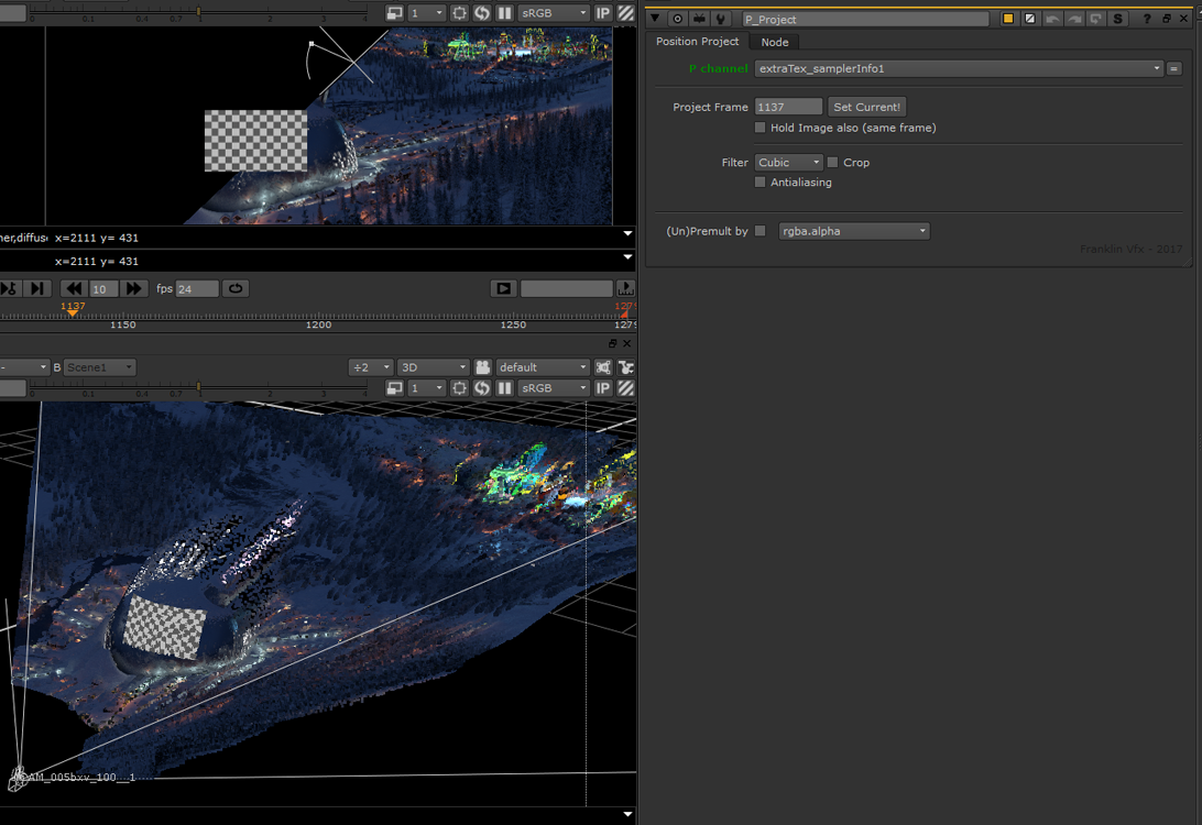
Projecting a basic checkerboard onto a terrain using the P_Project gizmo. (Source).
Next, let’s look at a special case when it comes to parallax:
The Nodal Pan
Typically, every camera move will have at least some parallax.
There is a notable exception to this, however, which you should be aware of:
A nodal pan camera move gives no parallax to the shot.
Rotating a camera around its no-parallax point, or nodal point, means there will be no shift in the position between the foreground and background objects in the scene.
For shots with this specific type of camera move, avoid adding parallax to any elements that you composite in, as they will appear to slide against the background.
Let’s continue looking at ways to add or match parallax:
2D Tracking
Another way of placing elements into a scene is to simply 2D track them in.
It might not always be as technically accurate as having a 3D scene, but it’s very often highly effective for achieving a realistic composite.
When you want to 2D track an element into a shot, confirm that you’re 2D tracking the correct plane of depth in the scan.
You normally have to track the area where you want to insert an element. And that means you may have to 2D track your scan several times if you want to insert elements at different depths.
For example, one track for the foreground, one for the midground, and one for the background.
A background element tracked into the shot using the foreground 2D track is unlikely to move correctly for its position in depth.
Sometimes, the features that are available to track in the scan won’t correspond with the depth plane where you want to place your element.
For example, if the background is a green screen that’s a few metres away, but you want to replace the green screen with a new background which is much further away – for example some distant mountains.
Ideally, you would then create a camera track for the scan and lay out Cards/geometry at the correct distances from the camera to get the right parallax for your elements.
However, it’s also possible to fake the parallax in 2D using a regular Tracker node:
Scaling A 2D Track
First, using a Tracker node, track features at a depth plane that is available – for example the tracking markers on a green screen.
Next, export a baked match-move from the Tracker node using the Export function at the bottom of the Tracker tab in the node’s properties: select Transform (match-move, baked) in the drop-down menu, and click Create.
This will create a Transform node with the match-move animation baked in.
To control the amount of transformation in the Transform node, let’s add a slider to its properties:
Click the little pen icon at the top of the properties panel and drag and drop a Floating Point Slider (the first icon in the newly revealed row of user knobs next to the pen icon) onto the properties of the Transform node.
Name the Floating Point Slider amount and label it Amount. The default range of 0 to 1 is fine to keep (which will represent 0%-100% transformation).
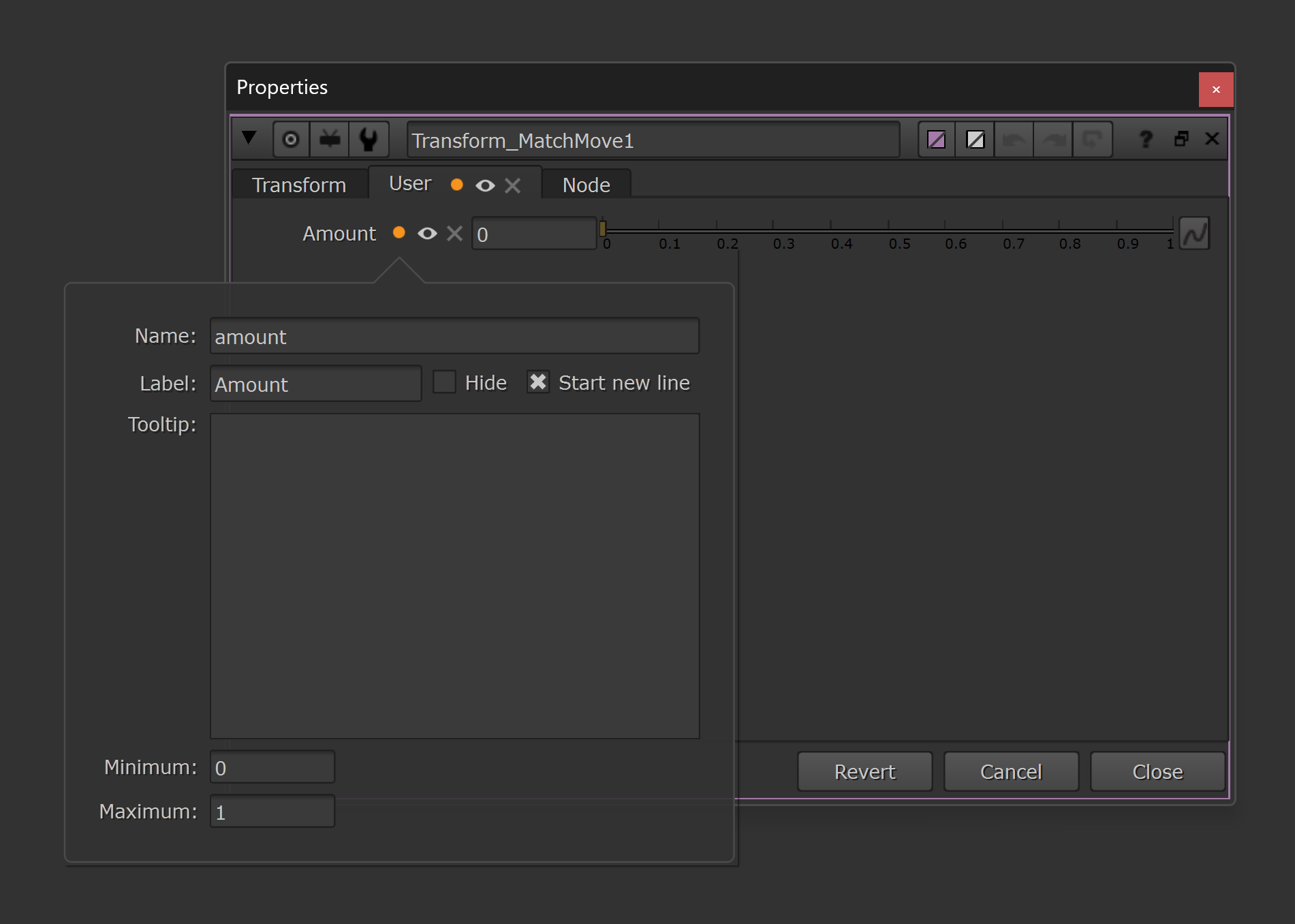
Creating a User tab with a Floating Point Slider knob called amount.
By multiplying the baked animation curves of the translation and rotation by our amount value, we can scale the curves based on the value that we set. We can do that using a simple expression:
In each of the translate.x, translate.y, and rotate knobs, add the following expression (right-click on the knobs and select Edit expression):
curve * amount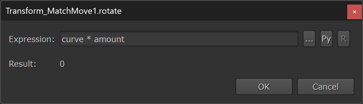
Adding the expression to the x and y translation and to the rotation.
– In the expression above, curve (which is a standard Nuke term that’s used in expressions) is referencing the baked animation curve’s value on the current frame, and amount is referencing the value that we set in the amount knob that we created earlier.
Now, if let’s say the translation in X is 20 pixels to the right on the current frame, and we set the amount to 0.5 (i.e. half), the expression would output:
20 * 0.5 = 10 – Which is half of 20, as expected.
This video shows what it looks like when you scale the translation up or down:
Modifying Tracking Data With Expressions in Nuke.
If the rotation is -10 degrees (i.e. 10 degrees clockwise) and the amount is set to 0.75 (i.e. three quarters), the expression would output:
-10 * 0.75 = -7.5 – Which is three quarters of -10, as expected.
Next, to scale the baked animation curve of the scale knob – which has a default value of 1 (as opposed to a default value of 0 for the translation and rotation knobs) – we have to make a little bit more advanced expression.
Because, we can’t simply multiply the animation curve by the amount like before – we have to consider the difference between the current scale value and the default scale value (i.e. 1).
For example, let’s say that the current scale value is 1.2, and we set the amount to 0.5 – i.e. we want half of the transformation. Halfway between 1 and 1.2 is 1.1. However, simply multiplying the animation curve’s value by the amount would give us 1.2 * 0.5 = 0.6 which is not the right value in this case.
Instead, we have to find the difference between the scale knob’s value and 1 (the default value), then multiply that difference by the amount to find the scaled difference. And finally, either add or subtract the result (i.e. the scaled difference) to/from 1, depending if the scale knob’s value was above or below 1.
To do that, add the following expression to the scale knob:
curve < 1 ? 1 - (1 - curve) * amount : 1 + (curve - 1) * amount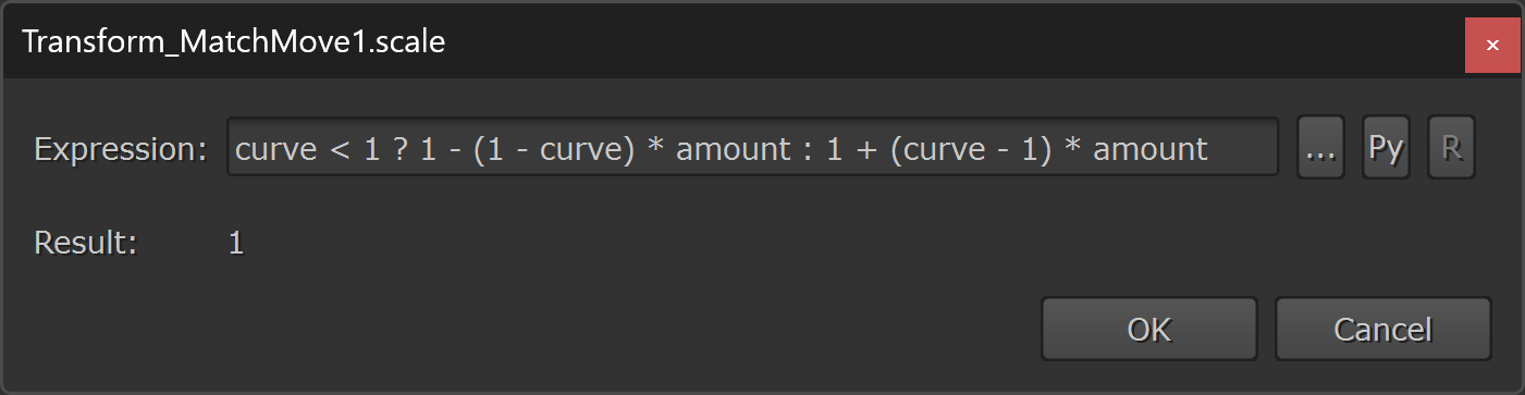
Adding the expression to the scale.
The expression above uses an if/else statement:
First, it checks if the value of the baked animation curve on the current frame is less than 1:
curve < 1 ?If it is, the expression will output 1 minus the scaled difference:
1 - (1 - curve) * amountIf it’s not (else), the expression will output 1 plus the scaled difference:
: 1 + (curve - 1) * amount So, using the previous example, if the current scale value is 1.2 (which is greater than 1), and the amount is 0.5, the expression will output:
1 + (1.2 - 1) * 0.5 = 1.1 – Halfway between 1 and 1.2, as we would expect.
Or, if the current scale value is 0.8 (which is less than 1), and the amount is 0.5, the expression will output:
1 - (1 - 0.8) * 0.5 = 0.9 – Halfway between 0.8 and 1, as we would expect.
The amount value doesn’t have to be between 0-1 (0%-100%). You could scale the transformation by for example 2 (200%) using the exact same expression above.
For example, if the current scale value is 1.2 (which is greater than 1), and the amount is 2, the expression will output:
1 + (1.2 - 1) * 2 = 1.4 – Which is twice as far away from 1 as 1.2 is, just as expected.
Or, if the current scale value is 0.8 (which is less than 1), and the amount is 2, the expression will output:
1 - (1 - 0.8) * 2 = 0.6 – Which is twice as far away from 1 as 0.8 is, just as expected.
The same logic applies to the expressions that we made in the translate and rotate knobs; multiplying by an amount greater than 1 (100%) will scale the baked animation curves’ values up accordingly.
And so, by using these expressions together with the amount slider, we can now freely scale the transformations up or down to our hearts content.
Which means, if you tracked some tracking markers at a nearby depth plane (e.g. a green screen), and you want to scale down the match-move to make your element appear further away, you could just reduce the amount.
An amount of 0.8 would give you 80% of the original camera movement, and an amount of 1.2 would give you 20% more camera movement.
So, you can adjust the amount value to dial in just the right amount of parallax for your element to sit into the scene.
You can even animate the amount.
This can for example be useful if you want to animate a stabilisation. Let’s say that there is a constant camera shake in your shot but you want the shot to start out smooth and ramp into the camera shake.
You could stabilise the shot, and then animate the amount from 1 to 0 in order to animate the camera shake back on.
Another way to scale a track is to use the Warp Transformations In Nuke technique.
– Disable the Mask section, and just adjust the IDistort node’s UV scale value to dial in the amount of transformation – just like we did before with the amount value.
To get accurate motion blur, however, you’d have to use a technique such as this one, or use a MotionBlur2D node to generate motion vectors for a VectorBlur. (Remember to scale the motion amount value in the VectorBlur by the UV scale value in the IDistort).
Yet another way for scaling the track is to use a dissolve expression:
First input’s values * mix + Second input’s values * (1 - mix)In our case, the ‘first input’ would be the baked animation curve’s value, and the ‘second input’ would be the knob’s default value. And the ‘mix’ would be our amount.
So, for the translation and rotation, the expression would become:
curve * amount + 0 * (1 - amount) which, because anything multiplied by 0 is 0, becomes:
curve * amount – the same as we saw before.
For the scale, the expression would become:
curve * amount + 1 * (1 - amount) which, because anything multiplied by 1 stays the same, becomes:
curve * amount + 1 - amount – also, the same as we saw before. Earlier, it was just written as 1 + (curve - 1) * amount, which, when you work it out, becomes the above.
And so, it turns out that we can simplify the whole if/else statement which we made for the scale value earlier, because this expression works both for when the baked animation curve's value is greater than 1 and for when it is less than 1.
By adjusting the amount slider like before, the expressions will scale the track.
And that wraps it up! I trust these techniques will make you more confident in creating and matching parallax in Nuke.
I hope you found this tutorial useful. For more Nuke tips & tricks, see Nuke.


