Lining Up Element Plates In Nuke
Two methods for accurately aligning an element plate to the main plate…

Two methods for accurately aligning an element plate to the main plate…
Use The LIDAR / Matchmove Geometry
I’ve previously covered how to line up CG/DMP renders between shots in a sequence. But how can we do the same with live-action element plates?
Crowd plates or other element plates will sometimes be filmed for use across a sequence of shots. The camera will usually be locked off, but not always, and it may not be in the exact same position or angle as in the main plates of the sequence.
To line up the perspective of an element plate with the main plate of a shot – and keep consistency across the sequence – you can use the LIDAR scan or the matchmove geometry of the set.
If you have a matchmove camera for the element plate, you can live-project the element plate using that, and render it out using the main camera.
Assuming the Matchmove department lined up each camera in world space.
If you don't have a matchmove camera for the element plate, you can overlay a wireframe render of the LIDAR or matchmove geometry using the main camera, and manually corner pin and line up the features of the element plate with the corresponding features in the main plate.
Let's look closer at each method:
Live-Project Method
For this first method, you essentially want to film the element plate using the main plate’s camera.
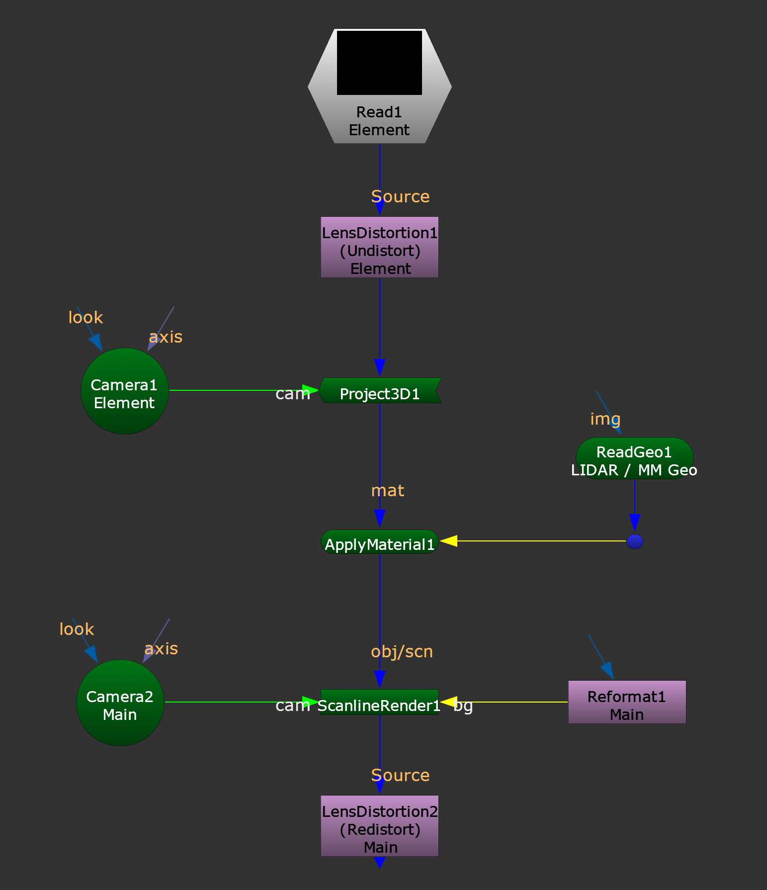
Live-projection setup.
Start by undistorting your element plate using the element plate camera’s lens undistortion.
Then, project this onto either the LIDAR or the matchmove geometry using a Project3D node.
Next, render this out using the main plate’s camera and format.
And finally, redistort the render using the main plate camera’s lens distortion.
Now, the projected element plate will be aligned with the main plate and you can composite it however you see fit.
Wireframe Overlay Method
For the second method, you’ll have to manually align the element plate.
However, by using a wireframe render of the LIDAR or the matchmove geometry, you’ll have visual guidelines and features to match up to which makes the alignment both easier and more accurate.
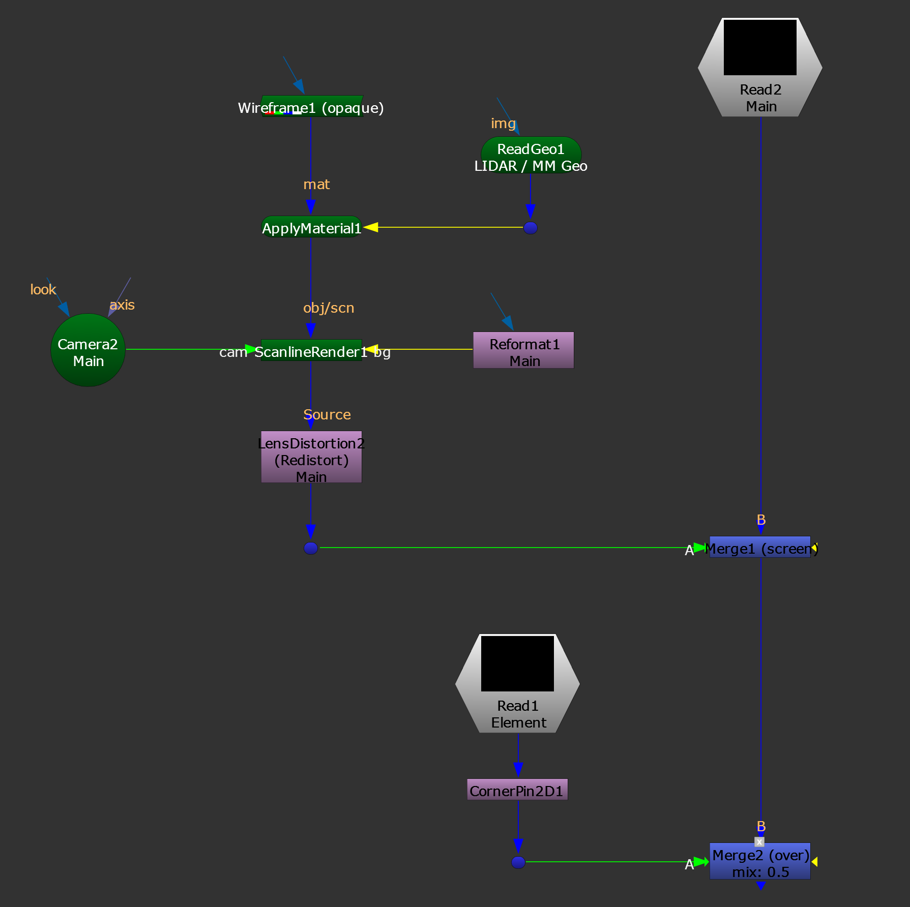
Wireframe setup for assisting with element alignment.
In this second setup, start by applying a Wireframe shader to the LIDAR or the matchmove geometry, and render that out using the main plate’s camera and format.
Redistort the render using the main plate camera’s lens distortion, and Merge (screen) this (A) over your main plate (B).
Now, you have a wireframe of the scene overlaid with your main plate. You can see where all the features of the scene are, even if they are for example partially blocked by a doorway in the main plate.
Merge (over) your element (A) with this wireframe overlay (B), and lower the mix value to for example 0.5.
Using a CornerPin node or another transformation node, align your element with the features in the wireframe overlay.
Finally, composite your element with the main scan however you see fit.
If the LIDAR geometry is too heavy to meaningfully work with in Nuke, you can instead line up Cards or other geometry to it, and use those instead.
I hope you found this tutorial useful. For more Nuke tips & tricks, see Nuke.