How To Calculate Reference Frames In Nuke
Choose your own reference frame for any animated transformations by using some basic maths…

Choose your own reference frame for any animated transformations by using some basic maths.
Origin
A reference frame is essentially the origin of all transformations. The source frame. It's the frame on which there is no change in the original transformation of an object.
Imagine a Transform node connected to a smoke element in Nuke. On the reference frame, the transformation values in the Transform node would be the default values. I.e., translate would be 0 in both x and y, rotate would be 0, scale would be 1 in both x and y, and skew would be 1 in both x and y.
Any animated transformations emanate outward from the reference frame. For example, 2D tracking data:
2D Reference Frame
Let's say you are working on a shot in which a person is walking down the street. The working frame range is 1001-1100; there is a camera move following the person in the shot, and you have a matte painting of a street sign which was painted on frame 1050.
If you track the street sign into the shot using a Tracker node, for example, you have to make sure the reference frame in the Tracker is set to frame 1050 for the matte painting to line up. Otherwise, you'd have to manually offset the transformations in order to line up the sign correctly.
💡 The matte painting was already lined up on frame 1050 by the matte painter, and so the transformations in the Tracker should be zeroed out on that frame.
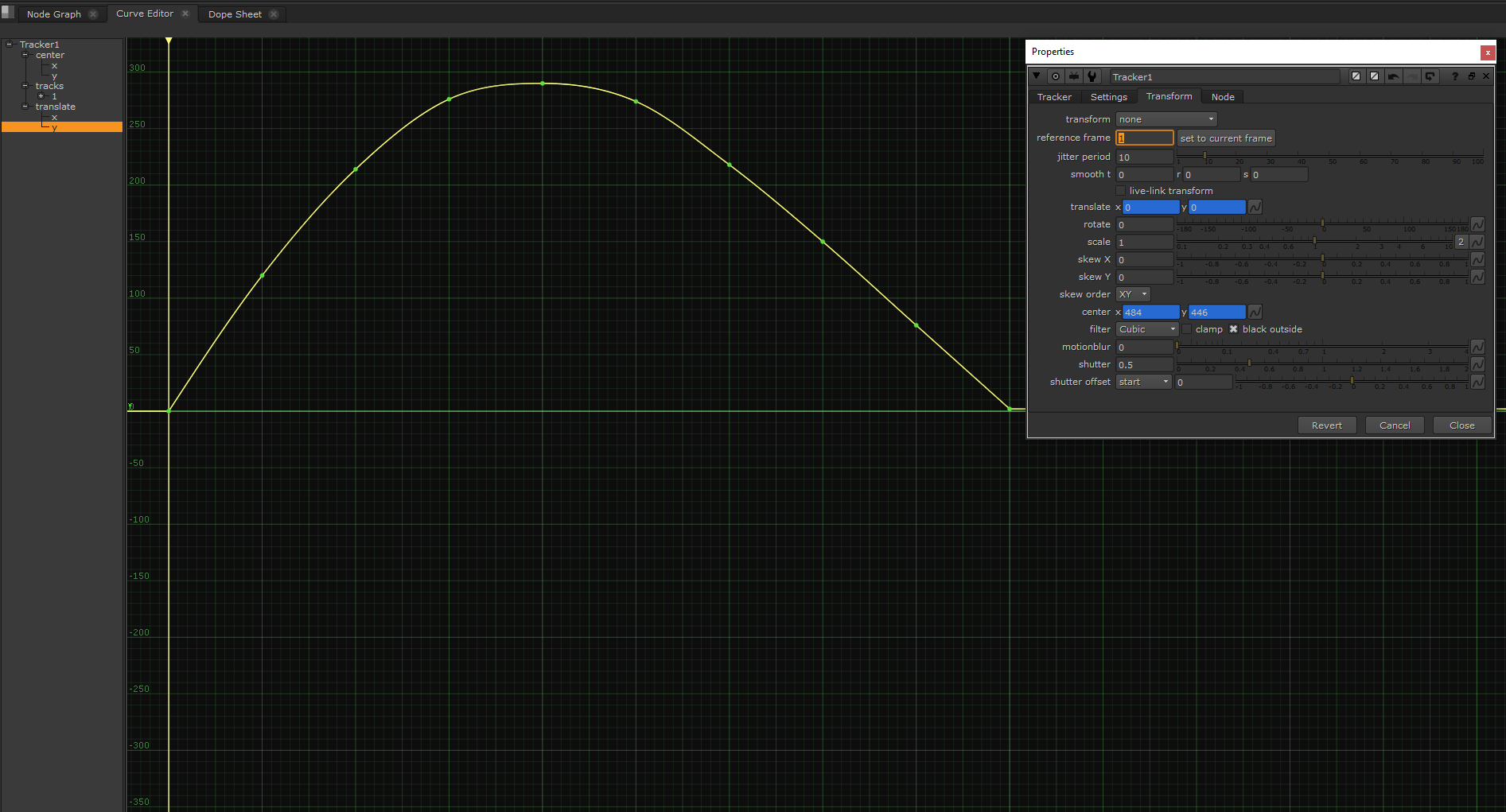
The reference frame is by default set to frame 1 in the Tracker node. That means the Tracker will invert the tracking values on frame 1, to zero them out, and offset the whole animation curve to compensate for the change on all keyframes.
By default, the reference frame is set to frame 1 in the Tracker node.
The animation curves in the Tracker stay (relatively) the same no matter which reference frame you select – they only get offset based on the values on the reference frame.
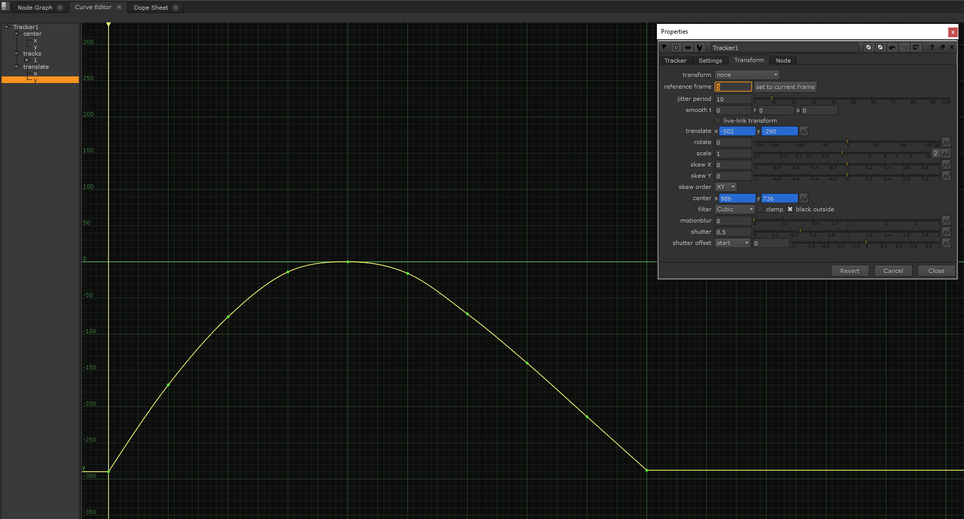
The animation curve is offset by choosing a different reference frame, but otherwise it stays the same.
If you track the aforementioned shot from frame 1001 to 1100, the Tracker will by default use the tracking values on frame 1001 to calculate the offset for the animation curves. That's because the values on frame 1001 will repeat all the way back to frame 1 (unless you have extrapolated the animation curve differently).
Setting the reference frame to frame 1050 will zero out the transformations on that frame instead, and offset the animation curve accordingly.
Automatically Offsetting The Animation Curve
So, how does the Tracker invert the values on the reference frame and calculate a new animation curve?
It’s very simple, and it does it automatically for you. Depending on which transformation it is inverting, the Tracker either uses subtraction or division to invert the values.
The translate and rotate values are inverted by subtracting the original values by themselves. A value subtracted by itself becomes 0. So, if something moves 100 pixels to the right, subtract 100 from the x translation to go back to the basic position.
The scale and skew values are inverted by dividing the original values by themselves. A value divided by itself becomes 1 (the value 0 is an exception here). So, if something is scaled up by 2, divide it by 2 again to go back to the basic size.
So, the Tracker either subtracts or divides the transformation values on all frames by the values on the reference frame. Which means, on the reference frame the translate and rotate values become 0, and the scale and skew values become 1. Ergo, no transformation.
💡 Check out 3D To 2D Tracking In Nuke for a tutorial on how to convert 3D tracking data into 2D tracks in a Tracker node, which lets you freely change the reference frame automatically by changing the reference_frame knob.
Manually Offsetting The Animation Curve
The Tracker node makes it easy to automatically invert the transformation values and offset the animation curve based on a reference frame. However, other nodes don’t have this handy function.
You can quite easily do it manually, though – for example if you want to change the reference frame of an animated Transform node.
Right-click on any animated transformation in the Transform node's properties, and select Edit expression. Since the transformation is animated, it will have an animation curve – and the expression will say curve. This expression simply retrieves the values of the animation curve on the current frame, for any respective frame you go to.
You can retrieve the values of the animation curve on a specific frame by typing the frame number in parentheses after the word curve in the expression. So, curve(1050) would give you the values of the animation curve on frame 1050.
Using the above expressions, you can zero out the values on the animation curve on any frame you want. Our reference frame was frame 1050, and so:
To invert the translate and rotate values on the reference frame, and offset the whole animation curve to match, use subtraction:
curve - curve(1050)
To invert the scale and skew values on the reference frame, and offset the whole animation curve to match, use division:
curve / curve(1050)
These expressions will shift the whole animation curve so that it is zeroed out on the reference frame 1050, specifically.
💡 If you want to connect other nodes in between – before you invert the transformations back – you can split out the inverse transformations. Copy the Transform node, and while on the reference frame, delete the animation on the transformations in the copy. Then tick the invert checkbox and place the inverted Transform node after your in-between nodes.
⚠️ Pitfall Alert
Exactly like the Tracker node does, the Transform node performs transformations in a specific order. That is, the reverse order of how the operations are listed in the node.
From top to bottom, the transformations are listed in the following order:
translate → rotate → scale → skew X → skew Y. (In the skew_order dropdown menu, you can choose whether to skew in X or Y first. By default it’s set to XY, i.e. X first, then Y).
And so, the order in which the Transform node actually performs the transformations is:
skew Y → skew X → scale → rotate → translate
(Or skew X → skew Y → scale → rotate → translate, if you choose YX in the skew_order dropdown menu).
Because of this specific order of operations, you have to tick the invert checkbox in the Transform node to correctly invert the transformations. Or, break the Transform node up into multiple Transform nodes, one for each transformation, and reverse their order in the pipe, like above. Only then will the values be inverted in the correct (reverse) order.
If you instead were to copy the Transform node, then connect the copy underneath it, and manually invert the values in the copy, the copy would not correctly invert the transformations of the original node – because the copy would still be performing the operations in the same order as the original Transform node (and not in reverse like it should).
Special Case: CornerPin
To change the reference frame of an animated CornerPin node, you have to consider both the to and from values. (Because in order to zero out any transformation, the corresponding to and from values have to be equal).
In the to1 x and y fields, add the following expression:
curve - curve(1050) + from1
In the to2, to3, and to4 x and y fields, replace the from1 with from2, from3, and from4.
Lastly, change the 1050 to your desired reference frame.
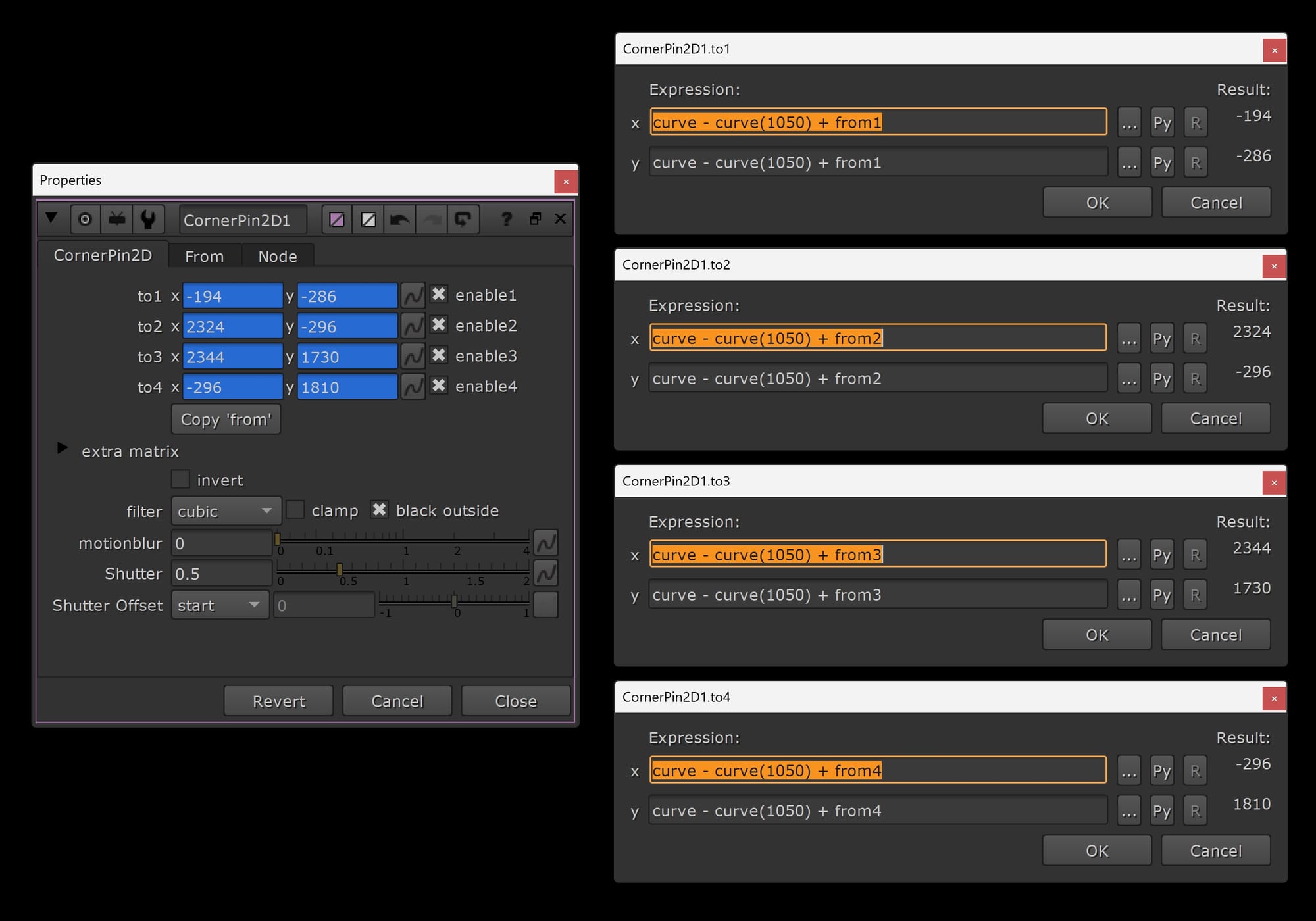
The expressions for changing the reference frame of an animated CornerPin to frame 1050.
3D Reference Frame
The basic approach to calculating a reference frame in the context of 2D transformations applies to 3D transformations as well; you just have one more dimension to account for.
That means, if you want to correctly invert the transformations, you now have to reverse both the transform order and the rotation order.
Let’s say you have some animated geometry and you want to change the reference frame. The same expressions we wrote before still apply:
To invert the translate and rotate values on the reference frame, and offset the whole animation curve to match, use subtraction:
curve - curve(1050)
To invert the scale and skew values on the reference frame, and offset the whole animation curve to match, use division:
curve / curve(1050)
These expressions will shift the whole animation curve so that it is zeroed out on the reference frame 1050, specifically.
⚠️ Pitfall Alert, Part 2
Keep in mind that, just like with the 2D transformations, 3D transformations also happen in the same specific order. And since there is one more dimension, there are more options to reverse.
If you again want to split out the inverse transformations in order to place other nodes in between, you can connect a TransformGeo node to your animated geometry, with an Axis node connected to the TransformGeo’s axis input.
Next, copy the transformation values from the animated geometry on the reference frame and paste them into the Axis node.
Then, in the Axis node:
Change all the translate and rotate values to their negative equivalents, e.g. 10 becomes -10, and -10 becomes 10.
Change the scale and skew values to 1 divided by the value, e.g. 2 becomes ½, and ½ becomes 2.
Change the transform order and rotation order to their opposites, e.g. from SRT to TRS, and from ZXY to YXZ.
You have now offset the animation curves of the animated geometry to reflect the new reference frame. Please note that, just like before, it’s crucial to reverse the order of the transformations correctly. So don’t forget that last step above.
Projections
Projections are a bit simpler when it comes to applying reference frames.
You only need to remember to either:
Framehold the projection camera on the reference frame that the matte painting was painted on.
Or:
Delete the animation in the projection camera on the reference frame.
That way, the projection stays correctly locked to the reference frame.
4x4 Transformation Matrix
3D nodes which apply transformations – such as the Camera, Axis, TransformGeo, and ReadGeo nodes – all use 4x4 matrices to apply the transformations under the hood.
And so another way to invert the transformations is to invert the 4x4 transformation matrix applied by the node. That requires a bunch of calculations, so let me save you some time and link a tool which does it for you:
https://www.nukepedia.com/gizmos/3d/inverse_axis
I hope you found this tutorial useful. For more Nuke tips & tricks, see Nuke.